Use Simulink Design Verifier for Systematic Model Verification
Control engineers in automotive and aerospace domains need to ensure underlying control algorithms have desired behavior throughout operational lifecycle.
Simulink® Design Verifier™ helps you perform systematic model verification to identify hidden design errors, prove properties, and generate test cases for functional testing. Simulink Design Verifier uses formal verification methods to test design correctness and to increase confidence in your design model that the production code generation uses. For example, engineers may perform verification and validation during the development lifecycle to ensure that:
The engine management system does not lead to undesired behaviors such as unintended acceleration or engine stalling during operation.
Advanced driver-assistance system (ADAS) applications that control the brakes and steering operate well under all conditions.
Autopilot systems respond correctly to all possible flight conditions and inputs.
Flight control systems are stable and responsive to prevent catastrophic failures during flight.
A model designer and test engineer use Simulink Design Verifier in the model development phase evolution to achieve verification and validation.
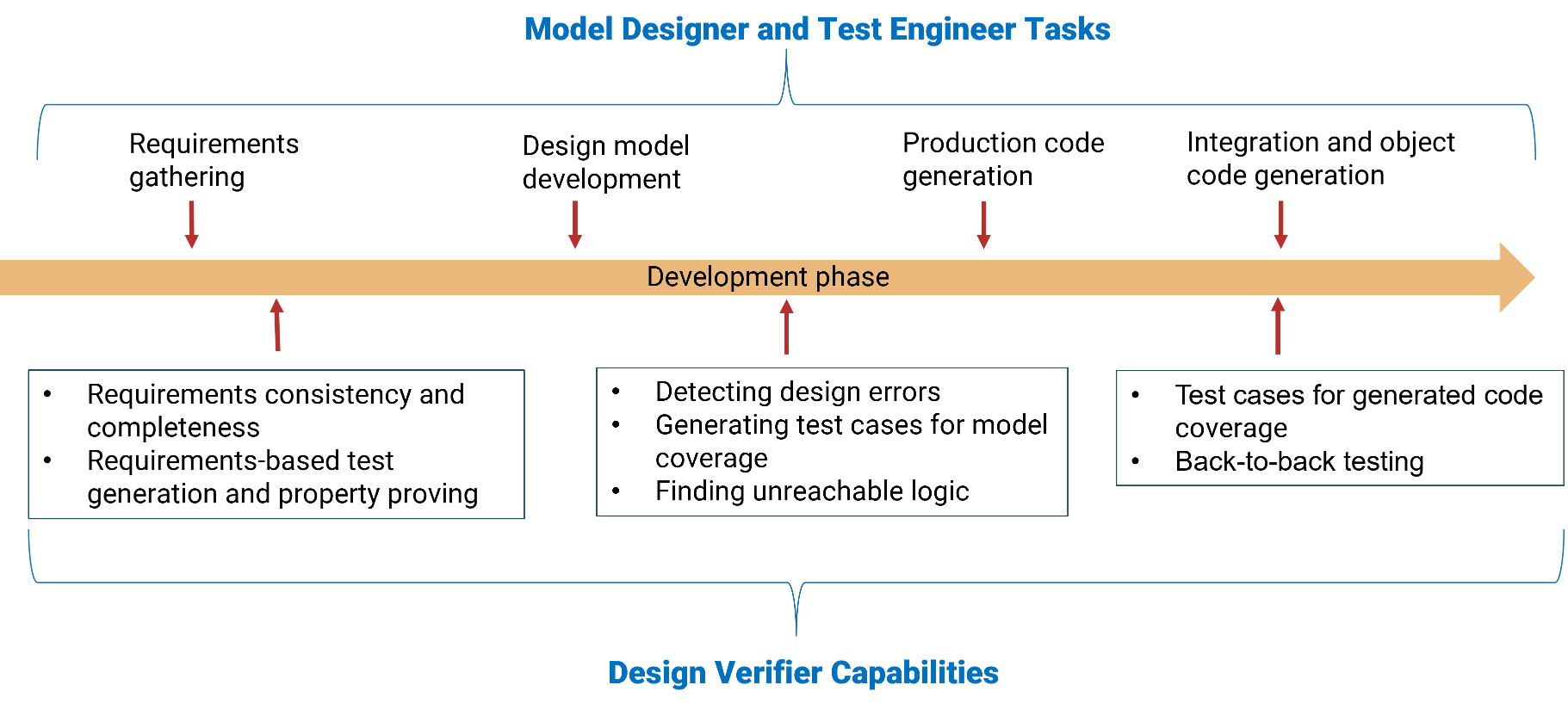
Capabilities of Simulink Design Verifier
Simulink Design Verifier offers features such as:
| Capability | Description |
|---|---|
| Analyze functional requirements |
For more information, see Use Specification Models for Requirements-Based Testing. |
| Test generation |
For more information, see Workflow for Test Generation. |
| Design error detection |
For more information, see What Is Design Error Detection? |
| Prove properties |
For more information, see Prove Model Properties |
| Incremental analysis, filtering, and justification |
|
Generated code analysis |
|
Certification or compliance | Achieve compliance with industry standards such as ISO 26262 for automotive or DO-178C for aerospace using the generated artifacts. |
How to Use Simulink Design Verifier
Using Simulink Design Verifier involves these key steps.
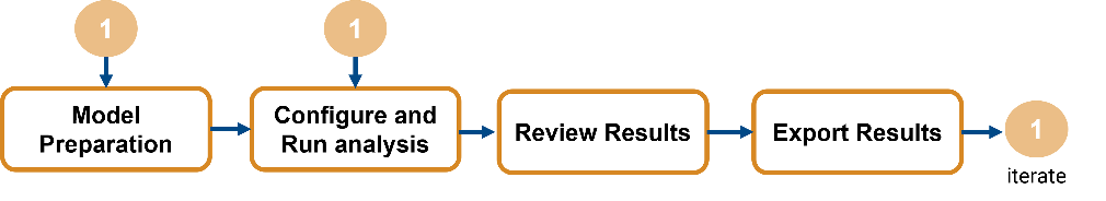
Model preparation: Prepare the model for analysis.
Select the analysis mode such as test case generation, design error detection, or property proving analysis.
Configure analysis parameters and check model compatibility with the analysis. For more information, see Analyze Model and Interpret Results.
Configure model settings and run analysis: Specify model settings and perform analysis relevant to your analysis needs.
Select maximum analysis time, coverage mode, run-time error mode, strategy, and other configuration parameters for the analysis.
Run the analysis.
Review results: View generated results.
Inspect results from the model highlighted by Simulink Design Verifier after its analysis is complete.
Review objectives statuses and define follow-up actions.
Generate analysis report.
Export Results: Use the insights gained from the results to refine the model or analysis setup.
Create harness for the simulation.
Export the test cases to Simulink Test™.
For more information, see Analyze Model and Interpret Results.
Simulink Design Verifier in Model-Based Design
This figure illustrates the capabilities of Simulink Design Verifier at various stages of the verification and validation workflow.
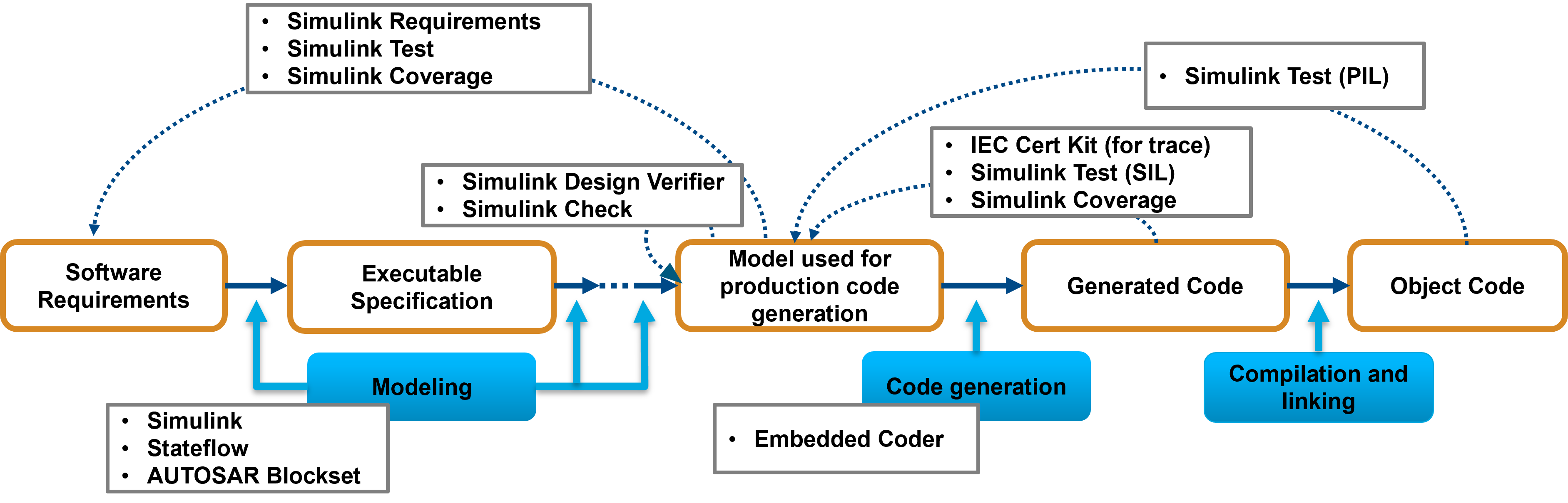
With Simulink Design Verifier, you can:
Identify hidden design errors, such as integer overflows or division by zero, and generate counterexamples to debug unintended functionalities. You can also justify or exclude model objects from analysis.
Verify model against requirements by using Requirements Toolbox™.
Achieve model coverage (Simulink Coverage) by generating test cases that satisfies model coverage objectives.
Perform code coverage (Embedded Coder) analysis by generating test cases for code generated by Embedded Coder®.
Extend existing test cases and achieve missing coverage.
Integrate test cases with Simulink Test to perform baseline and equivalence testing.
Support industry standards through the IEC Certification Kit (for IEC 61508 and ISO 26262) and DO Qualification Kit (for DO-178).
Simulink Design Verifier also supports industry standards compliance through the IEC Certification Kit (for IEC 61508 and ISO 26262), as well as the DO Qualification Kit (for DO-178).