Signal Types
Multiple types of signals can connect the blocks in a model. For example, a model may contain a control signal to initiate the execution of a block and buses to simplify line routing.
This table summarizes the types of Simulink® signals.
| Name | Description |
|---|---|
| Array | Nonscalar signal with one or more dimensions. |
| Array of buses | Array that contains nonvirtual buses. |
| Bus | Composite signal with name-based signal access. |
| Composite signal | Signal composed of other signals. See Composite Signals. |
| Concatenated signal | Nonvirtual vector, matrix, or array with index-based signal access. |
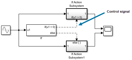
| Control signal | Signal used by a block to initiate the execution of another block. For example, a signal that executes a function-call subsystem or an action subsystem. See Control Signals. |
| Matrix | Two-dimensional nonscalar signal. |
| Multidimensional (N-D) signal | Array with three or more dimensions. |
| Mux signal | Virtual vector with index-based signal access. |
| Nonscalar signal | Signal with at least one dimension, such as a vector (1-D), matrix (2-D), or multidimensional array (N-D). |
| Nonvirtual signal | Signal that plays an active role in simulation and code generation. See Virtual and Nonvirtual Signals. |
| Scalar signal | Signal that supports only one value at a time. |
| Variable-size signal | Signal whose size (the number of elements in a dimension), in addition to its values, can change during a model simulation. |
| Vector | One-dimensional nonscalar signal. |
| Virtual signal | Signal that represents another signal or set of signals. See Virtual and Nonvirtual Signals. |
Note
Signals may also have application-specific types, such as a local wind velocity. To assign or validate the unit, minimum value, maximum value, dimensions, and other properties of a signal based on an application-specific type, see Specify Common Set of Signal Properties as Value Type.
Control Signals
A control signal is a signal used by a block to initiate the execution of another block. For example, a signal that executes a function-call or action subsystem is a control signal. When you update or simulate a block diagram, Simulink uses a dash-dot pattern to draw lines that represent the control signals.

Composite Signals
You can group multiple signals in a composite signal, route the signal from block to block, and extract the constituent signals where needed. When you have many parallel signals, composite signals can simplify the appearance of a model and clarify generated code. Composite signals can be virtual or nonvirtual.
For more information on composite signals, see Composite Interface Guidelines.
Virtual and Nonvirtual Signals
A virtual signal is a signal that graphically represents other signals or parts of other signals. Virtual signals do not exist in generated code. Some blocks, such as the Mux block, always generate virtual signals. Others, such as the Bus Creator block, can generate either virtual or nonvirtual signals. A signal is virtual if the block that generates it is virtual.
A nonvirtual signal is a signal that plays an active role in simulation and code generation. Some blocks, such as the Vector Concatenate block, always generate nonvirtual signals. A signal is nonvirtual if the block that generates it is nonvirtual.
For information on virtual and nonvirtual blocks, see Nonvirtual and Virtual Blocks.