Configure Model Layout
You can organize block diagrams by changing the position and orientation of model elements.
You can move signal lines by dragging them.
You can move, rotate, and flip blocks.
For some blocks, such as the Subsystem block, you can change the port order.
You can change the block diagram layout manually, or you can have the software can arrange it for you.
For information about how to organize blocks into subsystems, see Group Blocks into Subsystems. For information about how to bundle signal lines, see Group Signals or Messages into Virtual Buses.
You can further configure the appearance of your diagram by resizing blocks. You can also change the width, height, or size of multiple blocks to match the dimensions of a block you select.
Improve Model Layout with Auto Arrange
To improve your diagram layout and appearance, on the Format tab, click Auto Arrange. Alternatively, press Ctrl+Shift+A.
This option:
Aligns blocks in your block diagram from left to right, starting with inputs and ending with outputs
Resizes blocks, such as the Constant block, to display long parameter values
Standardizes block size among similar blocks
Straightens signal lines by moving blocks
You can also auto arrange the block diagram in a model programmatically.
Load the model using the
load_systemfunction.Auto arrange the block diagram using the
Simulink.BlockDiagram.arrangeSystemfunction.
Alternatively, you can try improving the shapes of individual signal lines. Select the signal line and, from the action bar, select Auto-route Line. The line redraws if a better route between model elements is possible.
You can try to improve multiple lines by using Auto-route Lines. To access Auto-route Lines from the action bar, select a block or select multiple model elements by dragging a box around the elements.
To change the alignment or distribution of blocks, draw a selection box around the blocks. Then, in the Simulink® Toolstrip, on the Format tab, use the buttons in the Distribute and Match sections to arrange the blocks.
Move Multiple Model Elements Simultaneously
To move multiple model elements while maintaining their spatial relationships, drag a selection box around the elements. Then, drag an edge of the selection box to a new position.
The contents of the selection box move as a unit. The relationship among lines, blocks, and other elements in the selection box remains the same as you move them. Line segments outside of the selection box reroute.
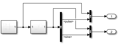
For example, consider this model.
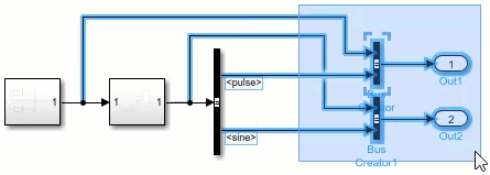
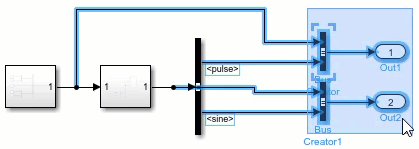
When you drag a selection box that includes line bends, the included line bends remain the same when you move the selection.
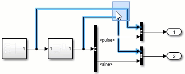
When you drag a selection box that excludes line bends, the excluded line bends may change when you move the selection.
To move multiple lines together, drag the selection box around the line segments you want to move.
Resize Blocks
To resize a block, pause your pointer on the block. The resize handles appear at the four corners of the block. Drag one of the resize handles outward to make the block larger, or drag inward to make the block smaller.
To resize one or more blocks to match the size of another block, follow these steps.
Select the block whose size you want the other blocks to match.
Press Shift and drag a selection box around the blocks you want to resize.
In the Simulink Toolstrip, on the Format tab, in the Match section, click the Match size
 button.
To resize one or more blocks to match either the width or height of another block, click
the Match width ![]() or Match Height
or Match Height ![]() button instead.
button instead.
Preserve Signal Line Shape When Moving and Resizing Blocks
By default, when you move or resize a block with three or more ports, any signal lines connecting the block to nearby blocks with one or two ports do not change shape. Instead, the connected blocks move. You can use this functionality, for example, to move a subsystem block without bending the signal lines to nearby ports.
If the block connects to a chain of consecutive blocks with one or two ports that are close to each other, the signal lines in the chain do not change their shape. Instead, the blocks move.
The affected signal lines and blocks highlight in green. The new functionality does not affect signal lines with branches or Simscape™ connections.
To temporarily turn the functionality off, hold the space bar while you move or resize a block. When you release the space bar, the functionality turns back on.
To turn the functionality off such that the functionality stays off across MATLAB® sessions, in the Simulink Editor, on the Modeling tab, from
Environment, unselect Preserve Alignment.
To turn the functionality back on, from Environment, select
Preserve Alignment again.
Flip or Rotate Blocks
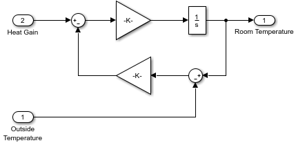
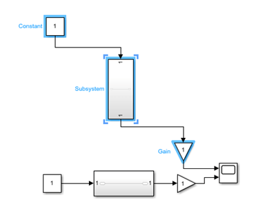
You can change the orientation of a block or a group of blocks by rotating blocks in 90-degree increments or by flipping the blocks. Rotating or flipping blocks can help them fit better in the block diagram, such as in feedback loops, where the blocks are connected to each other in a loop. You might also need to rotate a block so that the block input ports align with output ports or to make better use of the model canvas.
The figure shows a Gain block flipped to simplify a feedback loop diagram.
To rotate a block, select the block. On the Format tab, click
Rotate 90 clockwise ![]() or Rotate 90 counterclockwise
or Rotate 90 counterclockwise ![]() .
.
Tip
Alternatively:
To rotate a block clockwise, press Ctrl+R.
To rotate a block counterclockwise, press Ctrl+Shift+R
Blocks automatically rotate when you place them on a signal line that has an orientation other than left to right. For example, if the signal goes from bottom to top and you place a block on it, the block rotates to align with the signal.
To flip a block, select the block and, on the Format tab, click
Flip left-right ![]() or Flip up-down
or Flip up-down ![]() . You can flip a block horizontally or vertically based on
the orientation of the block ports. For example, if the ports are on the sides, the block
flips left to right.
. You can flip a block horizontally or vertically based on
the orientation of the block ports. For example, if the ports are on the sides, the block
flips left to right.
Tip
Alternatively, to flip a block horizontally, press Ctrl+I.
To rotate or flip a group of blocks, select multiple blocks before rotating or flipping them. You can only flip groups of blocks to the left or right.
After you rotate or flip a group of blocks, you can improve the readability of the block diagram by editing the signal lines. The Auto Arrange option might improve the appearance of signals. (For information on rotation with multiple ports, see Identify Port Location on Rotated or Flipped Block.)
For example, suppose you rotate these selected blocks clockwise.
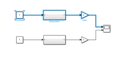
After you rotate the blocks, some model elements might overlap.
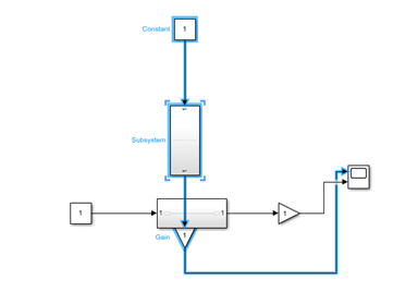
With the blocks and signals selected, on the Format tab, click Auto Arrange.
Identify Port Location on Rotated or Flipped Block
Rotating moves block ports from the sides to top and bottom or the reverse, depending on the placement of the ports. The resulting positions of the block ports depend on the block port rotation type.
Rotating can reposition the ports on some blocks to maintain left-to-right or top-to-bottom port numbering order. A block whose ports are reordered after a rotation has the default port rotation type. This policy helps to maintain the left-right and top-down block diagram orientation convention used in control system modeling applications. The figure shows the effect of clockwise rotation on a block with the default port rotation policy.
A masked block can specify that ports keep their order after rotation (see Icon drawing commands). These blocks have a physical port rotation type. This policy helps when designing blocks to use when modeling physical systems and other applications where diagrams do not have a preferred orientation. The figure shows the effect of clockwise rotation on a block with a physical port rotation type.
Flipping a block moves the ports to the opposite side of the block, creating a mirror image, regardless of port rotation type.
Move Ports
You can put ports in any order on any side of these blocks:
Subsystem block
Subsystem Reference block
Model block
Chart (Stateflow) block
Truth Table (Stateflow) block
State Transition Table (Stateflow) block
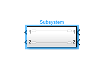
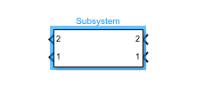
You can move ports by clicking and dragging the port.
For Subsystem blocks, the port index will automatically be renumbered after each move. For port label editing on Subsystem blocks, see Edit Port Labels on Subsystem Blocks.
You can drag a port to any side of a Subsystem block.
You cannot drag ports on masked or linked Subsystem blocks.
Related Topics
You can also select a web site from the following list:
Americas
- América Latina (Español)
- Canada (English)
- United States (English)
Europe
- Belgium (English)
- Denmark (English)
- Deutschland (Deutsch)
- España (Español)
- Finland (English)
- France (Français)
- Ireland (English)
- Italia (Italiano)
- Luxembourg (English)
- Netherlands (English)
- Norway (English)
- Österreich (Deutsch)
- Portugal (English)
- Sweden (English)
- Switzerland
- United Kingdom (English)