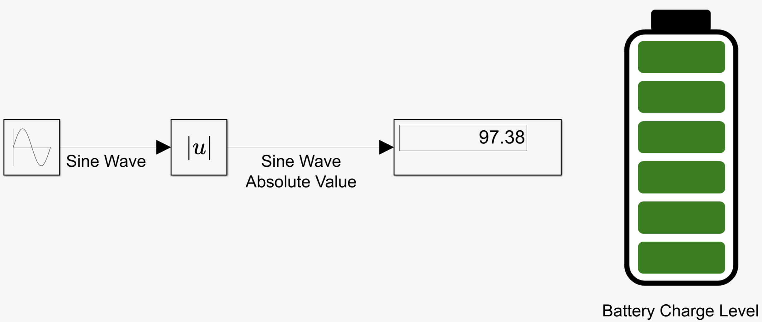
Main Content

MultiStateImage

R2026b

Display images based on signal values on block with customizable appearance

Since R2026b

  • MultiStateImage block

Libraries:
Simulink / Dashboard / Customizable Blocks

Description

The MultiStateImage block displays images based on the connected signal value. There is a MultiStateImage block in the Dashboard library and in the Customizable Block library. This page pertains to the block in the Customizable Blocks library. When you use the MultiStateImage block in the Customizable Blocks library, you can modify the appearance of the block to resemble a real indicator in your system. Use the MultiStateImage block with other dashboard blocks to build an interactive dashboard of controls and indicators for your model.

To configure the MultiStateImage block, specify one or more states. States pair images you provide with either values or with ranges of values you specify. When the value of the connected signal matches a state value or falls within a state value range, the MultiStateImage block displays the image for that state. When the value of the connected signal does not match any state values or fall within any state value ranges, the MultiStateImage block displays a default image you specify.

Customize MultiStateImage Blocks

When you add a MultiStateImage block to your model, the block is preconfigured with a default design. You can use the block with the default design or customize the appearance of the block.

To customize the appearance of the block, use design mode. After selecting the block, you can enter design mode in one of three ways:

  • In the Simulink® Toolstrip, on the block-specific tab, click Edit.

  • In the Property Inspector, on the Design tab, click Edit.

  • Pause on the ellipsis that appears over the block and click the Edit Custom Block button .

In design mode, you can use the toolbar above the block to customize the states. To access additional customization options or to enter exact values for design settings, use the Design tab in the Property Inspector.
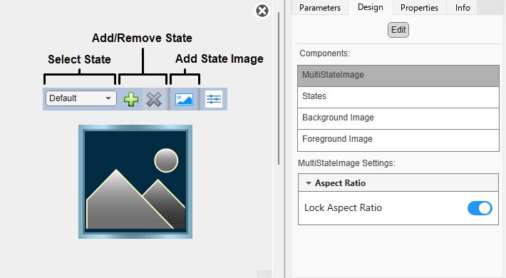
Customizable MultiStateImage block in design mode with the toolbar and the Design tab in the Property Inspector visible.

When you customize a MultiStateImage block, you configure the block appearance for each state. To select a state to customize, use the drop-down list in the toolbar. Alternatively, in the Property Inspector, on the Design tab, select the States component, and then select from the Select State list. To add a state, in the toolbar, click the Add State button . To delete a state, click the Remove State button .

Design Mode Actions that Customize the Selected State

ActionAvailable in ToolbarAvailable in Design Tab

Specify the state value as a number or a range.

NoYes
Add or remove states.YesYes

Upload or replace the image for the state. Supported image file formats include PNG, JPEG, BMP, TIFF, SVG, and GIF.

YesYes
Change the size of the image.NoYes
Change the position of the image.NoYes
Lock the aspect ratio of the image.NoYes

In addition to customizing the block design using the toolbar and Design tab, you can resize and reposition the image interactively in the canvas. To resize the image for a specific state, select the state in the toolbar, and then resize or reposition the image.

Design Mode Actions that Apply to All States

ActionAvailable in ToolbarAvailable in Design Tab

Upload a background image.

NoYes

Set a solid background color.

NoYes

Upload a foreground image.

NoYes

To exit design mode, click the X in the upper right of the canvas.

Connect Dashboard Blocks

This block is a display block — a block that connects to a signal and visualizes its value.

Dashboard blocks do not use ports to connect to model elements. Instead, use connect mode. To enter connect mode on an unconnected block, pause on the block you want to connect and click the Connect button . To enter connect mode on a connected block, select the block, pause on the ellipsis that appears (…), and in the action menu that expands, click the Connect button.

In connection mode, select the signal line to which you want to connect. From the list that appears, select the signal to which you want to connect. Then, pause on the dashboard block and click the Done Connecting button . To see the dashboard block display the value of the connected signal, run the simulation.

For more information about connecting dashboard blocks, see Connect Dashboard Blocks to Simulink Model.

You can also connect dashboard blocks to a Stateflow® chart. For more information, see Connect Dashboard Blocks to Stateflow (Stateflow).

This animation shows how to connect the MultiStateImage block to your model.
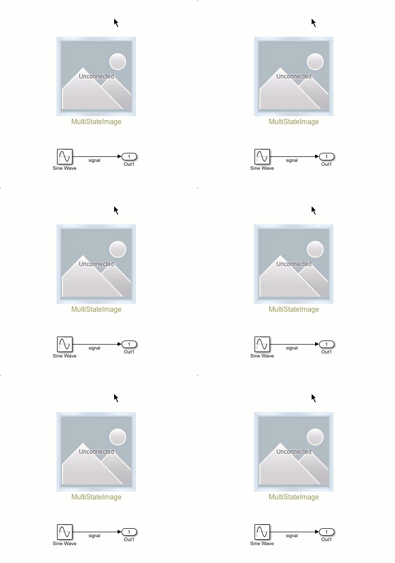
An unconnected Knob block connects to a Constant block.

Examples

Limitations

  • Except for the Dashboard Scope block and the Display block, dashboard blocks can connect only to real scalar signals.

  • You cannot use the Connection table in the Block Parameters dialog box to connect a dashboard block to a block that is commented out. When you connect a dashboard block to a commented block using connect mode, the dashboard block does not display the connected value until you uncomment the block.

  • Dashboard blocks cannot connect to model elements inside referenced models.

  • When you simulate a model hierarchy, dashboard blocks inside referenced models do not update.

  • Dashboard blocks do not support rapid accelerator simulation.

  • During simulation, you cannot connect a dashboard block to Stateflow chart data or state activity.

  • You cannot programmatically connect a dashboard block to Stateflow chart data or state activity.

  • Some signals do not have data available during simulation due to block reduction or optimization for accelerator mode simulations. To view such a signal using a dashboard block, mark the signal for logging.

Parameters

expand all

Use the Property Inspector and the Block Parameters dialog box to specify the values of the block parameters. To set the core parameters of the dashboard block, use the Block Parameters dialog box or the Parameters tab in the Property Inspector. To customize the block, use the Design tab in the Property Inspector. To open the Block Parameters dialog box for a block, double-click the block. To open the Property Inspector, on the Modeling tab, under Design, select Property Inspector.

Parameters Tab of Property Inspector

To set the core parameters of the dashboard block, select the block, open the Property Inspector and click the Parameters tab.

Signal

This block is a display block — a block that connects to a signal and visualizes its value. Dashboard blocks do not use ports to connect to model elements. Instead, use connect mode, the Simulink Toolstrip, or the Connection table in the Block Parameters dialog box. For information, see Connect Dashboard Blocks to Simulink Model.

To connect a display block to a signal using the Connection table:

  1. Select the block.

  2. In the Property Inspector, on the Parameters tab, click Connect or Change.

  3. Select the signal line to which you want to connect.

  4. In the table that appears, select the signal.

  5. Click Apply.

You can also connect dashboard blocks to a Stateflow chart. For more information, see Connect Dashboard Blocks to Stateflow (Stateflow).

Programmatic Use

You can programmatically connect a display block to a signal. Define a Simulink.HMI.SignalSpecification object that represents the signal. Then, set the value of the Binding parameter to the object. To set the value of the Binding parameter, use the set_param function.

For example, suppose the model named vdp contains a Circular Gauge block named myGauge and a signal named x1. To connect the block to the signal, use this code.

blockPath = "vdp/myGauge";
signalPath = "vdp/x1";

myObj = Simulink.HMI.SignalSpecification;
myObj.BlockPath = Simulink.BlockPath(signalPath);

set_param(blockPath,Binding=myObj)
Parameter: Binding
Values: Simulink.HMI.SignalSpecification object

Example: set_param(gcb,Binding=myObj)

Main

You can display the name of the element connected to the dashboard block in a label positioned at the top or bottom of the block, or you can hide the label. To show the label, specify the label position. To hide the label, select Hide.

Note

When the dashboard block is not connected to an element, the label is blank.

Programmatic Use

To set the block parameter value programmatically, use the set_param function.

Parameter: LabelPosition
Values: 'Hide' (default) | "Hide" | "Bottom" | "Top"

Example: set_param(gcb,LabelPosition="Top")

Select this parameter to maintain the aspect ratio when resizing the block in the Simulink canvas.

When the aspect ratio is locked, adding a new background image changes the aspect ratio of the block to match the aspect ratio of the background image. When the aspect ratio is unlocked and you add a new background image, the image resizes to fit the block without changing the block aspect ratio.

When the aspect ratio is locked, pressing Shift while resizing a block temporarily unlocks the aspect ratio. When you release Shift, the aspect ratio locks. When the aspect ratio is unlocked, pressing the Shift key while resizing a block temporarily locks the aspect ratio. When you release Shift, the aspect ratio unlocks.

States

You can specify ranges of signal values that activate the states. Select Specify State Values as Ranges and specify the minimum and maximum of the value range that activates each state.

Programmatic Use

To set the block parameter value programmatically, use the set_param function.

Parameter: StateValueType
Values: 'Discrete' (default) | "Discrete" | "Range"

Example: set_param(gcb,StateValueType="Range")

Each state pairs a Value with an Image.

  • Value — Connected signal value or range of signal values that trigger the MultiStateImage block to display the specified image. To specify a range of values, select Specify State Values as Ranges and specify the minimum and maximum of the range of values that activates each state.

    If the maximum of one range is the same as the minimum of another range, the value is assigned to whichever state comes first in the list of states. For example, if State 1 has the range [5 10] and State 2 has the range [0 5], when the connected signal has a value of 5, the MulitStateImage block displays the State 1 image because State 1 precedes State 2 in the list of states.

  • Image — Image to display when the connected signal value matches a State value. Supported image file formats include PNG, JPEG, BMP, TIFF, SVG, and GIF.

The [undefined] state specifies the image the MultiStateImage block displays when the connected signal value does not match any of the values specified in the States table.

To add or replace an image, in the Property Inspector, on the Parameters tab, in the States section, in the Image column, double-click the placeholder image or existing image and choose a new image file. To remove an image, pause on the image file and click the X that appears in the upper right corner.

Programmatic Use

To set the block parameter value programmatically, use the set_param function.

Specify the value of the States parameter as an array of structures, where each structure represents a state. Each structure contains these fields:

  • Value — State value, specified as a scalar when Specify State Values as Ranges is turned off, and as a vector of the form [min max] when Specify State Values as Ranges is turned on, where min and max are the minimum and maximum values of the range

  • Image — Data URL of the state image, specified as a character vector. A data URL has this format.

    data:image/<format>;base64,<data>

    <format> is the Multipurpose Internet Mail Extensions (MIME) subtype of the image, for example, png, jpeg, svg+xml,or gif.

    <data> is the Base64-encoded image data.

For example, suppose you want the currently selected MultiStateImage block to display image1.png when the connected signal has a value of 1 and image2.png when the connected signal is 2. Define the two states as in this code.

fid = fopen("image1.png","r");
imageData1 = fread(fid,"*uint8");
fclose(fid);

fid = fopen("image2.png","r");
imageData2 = fread(fid,"*uint8");
fclose(fid);

state1.Value = 1;
state1.Image = ['data:image/png;base64,',matlab.net.base64encode(imageData1)];
state2.Value = 2;
state2.Image = ['data:image/png;base64,',matlab.net.base64encode(imageData2)];
myStates = [state1 state2];

set_param(gcb,States=myStates)

Now suppose you want the block to display image1.png when the connected signal falls in the range [0 10] and image2.png when the signal falls in the range (0 20]. To implement these states, use this code.

fid = fopen("image1.png","r");
imageData1 = fread(fid,"*uint8");
fclose(fid);

fid = fopen("image2.png","r");
imageData2 = fread(fid,"*uint8");
fclose(fid);

set_param(gcb,StateValueType="Range");

state1.Value = [-10 0];
state1.Image = ['data:image/png;base64,',matlab.net.base64encode(imageData1)];
state2.Value = [0 20];
state2.Image = ['data:image/png;base64,',matlab.net.base64encode(imageData2)];
myStates = [state1 state2];

set_param(gcb,States=myStates)

Note that if the connected signal has a value of 0, the block is in state 1 because it is the first state in the list of states to include that value in its range.

Parameter: States
Values: N-by-1 structure array, where N is the number of states and each structure has the fields Value and Image

Example: set_param(gcb,States=myStates)

The DefaultImage parameter specifies the image for the MultiStateImage block when the value of the connected signal does not match any of the specified state values.

Parameter: DefaultImage
Values: '' (default) | data URL specified as a character vector

Example: set_param(gcb,DefaultImage=['data:image/png;base64', matlab.net.base64encode(imageData)])

Design Tab of Property Inspector

To customize the dashboard block, open the Property Inspector, click the Design tab, and click Edit.

MultiStateImage

Select this parameter to maintain the aspect ratio when resizing the block in the Simulink canvas.

When the aspect ratio is locked, adding a new background image changes the aspect ratio of the block to match the aspect ratio of the background image. When the aspect ratio is unlocked and you add a new background image, the image resizes to fit the block without changing the block aspect ratio.

When the aspect ratio is locked, pressing Shift while resizing a block temporarily unlocks the aspect ratio. When you release Shift, the aspect ratio locks. When the aspect ratio is unlocked, pressing the Shift key while resizing a block temporarily locks the aspect ratio. When you release Shift, the aspect ratio unlocks.

States

Select the state to configure from the drop-down list in the Select State section of the States component. You can use a customizable MultiStateImage block to design a block with one or more states. Click + to add another state. Click X to delete the current state.

Each state pairs a Value with an Image.

  • Value — Connected signal value or range of signal values that trigger the MultiStateImage block to display the specified image. To specify a range of values, select Specify State Values as Ranges and specify the minimum and maximum of the range of values that activates each state.

    If the maximum of one range is the same as the minimum of another range, the value is assigned to whichever state comes first in the list of states. For example, if State 1 has the range [5 10] and State 2 has the range [0 5], when the connected signal has a value of 5, the MulitStateImage block displays the State 1 image because State 1 precedes State 2 in the list of states.

  • Image — Image to display when the connected signal value matches a State value. Supported image file formats include PNG, JPEG, BMP, TIFF, SVG, and GIF.

The [default] state specifies the image that the MultiStateImage block displays when the connected signal value does not match any of the values specified in the States table.

Tips

You can also configure the values and images of the states for the block using the Parameters tab in the Property Inspector.

Programmatic Use

To set the block parameter value programmatically, use the set_param function.

Specify the value of the States parameter as an array of structures, where each structure represents a state. Each structure contains these fields:

  • Value — State value, specified as a scalar when Specify State Values as Ranges is turned off, and as a vector of the form [min max] when Specify State Values as Ranges is turned on, where min and max are the minimum and maximum values of the range

  • Image — Data URL of the state image, specified as a character vector. A data URL has this format.

    data:image/<format>;base64,<data>

    <format> is the Multipurpose Internet Mail Extensions (MIME) subtype of the image, for example, png, jpeg, svg+xml,or gif.

    <data> is the Base64-encoded image data.

For example, suppose you want the currently selected MultiStateImage block to display image1.png when the connected signal has a value of 1 and image2.png when the connected signal is 2. Define the two states as in this code.

fid = fopen("image1.png","r");
imageData1 = fread(fid,"*uint8");
fclose(fid);

fid = fopen("image2.png","r");
imageData2 = fread(fid,"*uint8");
fclose(fid);

set_param(gcb,StateValueType="Range");

state1.Value = 1;
state1.Image = ['data:image/png;base64,',matlab.net.base64encode(imageData1)];
state2.Value = 2;
state2.Image = ['data:image/png;base64,',matlab.net.base64encode(imageData2)];
myStates = [state1 state2];

set_param(gcb,States=myStates)

Now suppose you want the block to display image1.png when the connected signal falls in the range [0 10] and image2.png when the signal falls in the range (0 20]. To implement these states, use this code.

fid = fopen("image1.png","r");
imageData1 = fread(fid,"*uint8");
fclose(fid);

fid = fopen("image2.png","r");
imageData2 = fread(fid,"*uint8");
fclose(fid);

set_param(gcb,StateValueType="Range");

state1.Value = [-10 0];
state1.Image = ['data:image/png;base64,',matlab.net.base64encode(imageData1)];
state2.Value = [0 20];
state2.Image = ['data:image/png;base64,',matlab.net.base64encode(imageData2)];
myStates = [state1 state2];

set_param(gcb,States=myStates)

Note that if the connected signal has a value of 0, the block is in state 1 because it is the first state in the list of states to include that value in its range.

Parameter: States
Values: N-by-1 structure array, where N is the number of states and each structure has the fields Value and Image

Example: set_param(gcb,States=myStates)

The DefaultImage parameter specifies the image for the MultiStateImage block when the value of the connected signal does not match any of the specified state values.

Parameter: DefaultImage
Values: '' (default) | data URL specified as a character vector

Example: set_param(gcb,DefaultImage=['data:image/png;base64', matlab.net.base64encode(imageData)])

Apply the settings of the default state to all other states. This option applies to all settings in the States component except for the settings in the Value and Image section.

You can specify ranges of signal values that activate the states. Select Specify State Values as Ranges and specify the minimum and maximum of the value range that activates each state.

Programmatic Use

To set the block parameter value programmatically, use the set_param function.

Parameter: StateValueType
Values: 'Discrete' (default) | "Discrete" | "Range"

Example: set_param(gcb,StateValueType="Range")

Each state pairs a Value with an Image. Specify the Value that activates the state selected in the Design tab.

Note

When you enable the Specify State Values as Ranges option, the Value parameter changes to the parameters Minimum and Maximum, which allow you to define a range by specifying its minimum and maximum values.

Each state pairs a Value with an Image. Upload or replace the Image for the state selected in the Design tab. You can upload a custom image in PNG, JPEG, BMP, TIFF, SVG, or GIF format.

Specify the horizontal offset of the left edge of the image from the left edge of the block as a fraction of the block width. Relative to the position of the image without offset, a negative offset moves the image left, and a positive offset moves the image right.

Specify the vertical offset of the top edge of the image from the top edge of the block as a fraction of the block height. Relative to the position of the image without offset, a negative offset moves the image up, and a positive offset moves the image down.

Specify the image width as a fraction of the block width.

Specify the image height as a fraction of the block height.

Enable this option to maintain the aspect ratio when resizing the image using the Property Inspector.

Background Image

For the block background, you can provide a background image or select a solid color. To select a solid background color, select this parameter. To provide a background image, clear this parameter.

Note

Changing the background color using the Format tab of the Simulink Toolstrip removes the background image and enables the Use Background Color parameter.

To use a solid background color, select the Use Background Color parameter. Then, choose a background color from the palette of standard colors, or specify a custom color.

Programmatic Use

To set the block parameter value programmatically, use the set_param function.

Parameter: BackgroundColor
Values: [r g b] vector with values between 0 and 1 formatted as a string or character vector

Example: set_param(gcb,BackgroundColor="[1 0 1]")

Specify the block background opacity as a scalar value from 0 to 1.

Specify the corner radius of the area covered by the block background color. The radius is a fraction of whichever is smaller, half the block width or half the block height.

Foreground Image

Specify the horizontal offset of the left edge of the image from the left edge of the block as a fraction of the block width. Relative to the position of the image without offset, a negative offset moves the image left, and a positive offset moves the image right.

Specify the vertical offset of the top edge of the image from the top edge of the block as a fraction of the block height. Relative to the position of the image without offset, a negative offset moves the image up, and a positive offset moves the image down.

Specify the width of the foreground image as a fraction of the block width.

Specify the height of the foreground image as a fraction of the block height.

Select this parameter to maintain the aspect ratio when resizing the image using the Property Inspector.

Block Characteristics

Data Types

Boolean | double | enumerated | fixed point | half | integer | single

Direct Feedthrough

no

Multidimensional Signals

no

Variable-Size Signals

no

Zero-Crossing Detection

no

Extended Capabilities

expand all

Version History

Introduced in R2026b