Main Content

Network Coupler (Constant Volume Chamber (TL))

Split network at a thermal liquid connection

Since R2022a

  • Network Coupler (Constant Volume Chamber (TL)) block

Libraries:
Simscape / Utilities / Network Couplers

Description

The Network Coupler (Constant Volume Chamber (TL)) block uses a volume of fluid to break the connection between two networks. If your existing network has a suitable volume of fluid already modeled, then replace it with the fluid network coupler block. Otherwise, introduce a new volume of fluid to the system using the Network Coupler (Constant Volume Chamber (TL)) block. Try to make the volume of fluid representative of the dimensions of the part of the system where you are dividing the network, for example, use the volume of a connecting pipe. If you make the volume too small, it would require smaller step sizes, which would make real-time deployment more difficult.

Both of the port interfaces of the Network Coupler (Constant Volume Chamber (TL)) block are implemented as pressure and temperature sources. Therefore, you cannot connect this block directly to another volume of fluid or pressure source because this would cause an Index-2 topology (for more information, see Avoiding Numerical Simulation Issues).

Working with the Block on the Model Canvas

When you add the block to your model and double-click it, the Network Coupler (Constant Volume Chamber (TL)) subsystem opens.

Network Coupler (Constant Volume Chamber (TL)) subsystem diagram

The Port 1 Interface block contains the dynamics that break the algebraic loop. Double-click this block to set most of the Network Coupler (Constant Volume Chamber (TL)) subsystem parameters and view the derived values.

However, unlike most of the other coupler blocks, the Port 2 Interface block also has two parameters, Volume (m^3) and Port cross-sectional area (m^2), that you need to set separately.

The Network Coupler (Constant Volume Chamber (TL)) block is based on the Foundation library Constant Volume Chamber (TL) block when it has two fluid ports exposed. The coupler block implements a constant volume chamber using two copies of the custom Simscape™ component partialChamberTL.ssc. Each of these partial chambers models the full chamber, but calculates only the derivatives of pressure and temperature due to flow into its fluid port. The coupler subsystem also contains two Simulink® integrators, one for pressure and one for temperature, that sum and integrate the derivatives from the two partial chambers. These Simulink integrators also break the respective algebraic constraint, one for pressure and one for temperature, that would have existed if connecting two fluid networks directly.

Note

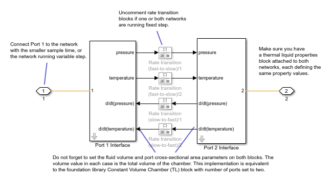
  • The Volume (m^3) parameter requested by the two subsystems is the total volume of the chamber in both cases, not half the volume.

  • The network coupler blocks break the transmission of fluid property data between the two networks. Therefore, you must attach a fluid properties block to both of the networks, setting fluid property values to be the same for each instance.

The rate transition blocks are, by default, commented through. Uncomment them if at least one of the coupled networks is running fixed step.

Using the Derived Values to Estimate Block Parameters

On the Analysis tab of the Port 1 Interface block dialog box, the Derived values section contains a list of recommended values that you can use when specifying block parameters. For example, use the Recommended max discrete sample time (s) derived value to verify that your Port 1 network discrete sample time (s) and Port 2 network discrete sample time (s) parameter values are within acceptable limits.

The derived values list is based on the chosen block configuration.

If both networks are running variable step, then the Analysis tab is empty, and there are no restrictions on the fluid volume value you specify.

If one or both networks are running fixed step, then the Analysis tab provides advice on the recommended maximum discrete sample time to use. To do this, you must provide some additional information about the connected networks:

  • Approximate connected network flow conductance, that is, the mass flow per unit pressure difference.

  • Approximate fluid density.

  • Approximate fluid bulk modulus.

These values only need to be approximate because they do not impact the model. They serve only to provide advice on the recommended maximum discrete sample time.

The Update button lets you recalculate the derived values after you change the parameters of the connected networks.

Ports

Conserving

expand all

If one of the coupled networks is running variable step, connect it to port 1 of the Network Coupler (Constant Volume Chamber (TL)) block. If both networks are running fixed step, connect this port to the network with the smaller sample time. If both networks are running variable step, or fixed step with the same step size, then the block polarity does not matter.

If one of the coupled networks is running variable step, connect port 2 of the Network Coupler (Constant Volume Chamber (TL)) block to the fixed-step network. If both networks are running fixed step, connect this port to the network with the larger sample time.

Parameters

expand all

Main

Specify the total volume of the chamber, in m^3. Because the top-level subsystem is unmasked, you need to set this parameter to the same value both for Port 1 Interface and Port 2 Interface blocks.

Specify the chamber inlet area normal to the direction of the flow, in m^2. Because the top-level subsystem is unmasked, you need to set this parameter to the same value both for Port 1 Interface and Port 2 Interface blocks.

Select how the coupled networks are sampled:

  • Variable step at ports 1 and 2 — Both networks are variable-step.

  • Variable step at port 1 and fixed step at port 2 — Network 1 is variable-step and Network 2 is fixed-step.

  • Fixed step both ports with common sample time — Both networks are fixed-step, with the same step size.

  • Fixed step both ports with faster sampling at port 1 — Both networks are fixed-step, with different step sizes.

Specify sample time for Network 1, in seconds.

Dependencies

To enable this parameter, set the Sampling type parameter to Fixed step both ports with common sample time or Fixed step both ports with faster sampling at port 1.

Specify sample time for Network 2, in seconds.

Dependencies

To enable this parameter, set the Sampling type parameter to Variable step at port 1 and fixed step at port 2 or Fixed step both ports with faster sampling at port 1.

Select this check box to enable the prediction (discrete->continuous) algorithm. For more information, see Prediction and Smoothing.

Dependencies

To display this option, set the Sampling type parameter to Variable step at port 1 and fixed step at port 2.

Select this check box to enable the smoothing (continuous->discrete) algorithm. For more information, see Prediction and Smoothing.

Dependencies

To display this option, set the Sampling type parameter to Variable step at port 1 and fixed step at port 2.

Specify time constant, in seconds, for the first-order filter that the smoothing algorithm uses to remove unwanted high-frequency information.

Dependencies

To enable this parameter, select the Use smoothing when connecting variable step to fixed step check box.

Select this check box to enable the prediction (slow->fast) algorithm. For more information, see Prediction and Smoothing.

Dependencies

To display this option, set the Sampling type parameter to Fixed step both ports with faster sampling at port 1.

Select this check box to enable the smoothing (fast->slow) algorithm. For more information, see Prediction and Smoothing.

Dependencies

To display this option, set the Sampling type parameter to Fixed step both ports with faster sampling at port 1.

The smoothing algorithm works by averaging the last N samples. You specify N by using this parameter.

Dependencies

To enable this parameter, select the Use smoothing when connecting fast to slow sample times check box.

Analysis

Specify approximate connected network flow conductance, that is, the mass flow per unit pressure difference, in kg/s/Pa.

Dependencies

To enable this parameter, set the Sampling type parameter to Variable step at port 1 and fixed step at port 2, Fixed step both ports with common sample time, or Fixed step both ports with faster sampling at port 1.

Specify approximate fluid density in the connected network, in kg/m^3.

Dependencies

To enable this parameter, set the Sampling type parameter to Variable step at port 1 and fixed step at port 2, Fixed step both ports with common sample time, or Fixed step both ports with faster sampling at port 1.

Specify approximate fluid bulk modulus in the connected network, in Pa.

Dependencies

To enable this parameter, set the Sampling type parameter to Variable step at port 1 and fixed step at port 2, Fixed step both ports with common sample time, or Fixed step both ports with faster sampling at port 1.

For information on how to use the Derived values section, see Using the Derived Values to Estimate Block Parameters.

Initial Conditions

Specify initial condition for the pressure in the chamber, in MPa.

Specify initial condition for the temperature in the chamber, in K.

Extended Capabilities

C/C++ Code Generation
Generate C and C++ code using Simulink® Coder™.

Version History

Introduced in R2022a

expand all