Wind Turbine

Libraries:
Simscape /
Driveline /
Engines & Motors
Description
The Wind Turbine block represents a wind turbine that converts wind motion into mechanical rotational energy. Wind turbines harness wind energy for electricity generation. Wind turbine development focuses on enhancing the efficiency, reliability, and cost-effectiveness of individual turbines, while wind turbine farm development involves the strategic placement of multiple turbines to optimize energy capture. You can use the block to simulate individual wind turbines and entire wind farms. You can analyze the turbine performance, power generation, and interactions in a wind farm, or the effect of different turbine geometries, configurations, control algorithms, and layout designs on wind farm performance and energy output.
You specify the incident wind velocity and collective blade pitch as inputs, and you can optionally output the thrust acting on the turbine. You can include the effects of thrust and inertia. Parameterize the block using tabulated power and thrust coefficients or airfoil lift and drag coefficients.
Parameterize by Power and Thrust Coefficients
When you set Parameterization to Tabulated
data for power and thrust coefficients, the block calculates the
coefficients of power and torque using table lookups, such that
where:
βRef is the reference pitch angle.
λRef is the reference tip speed ratio.
CP,Ref and CT,Ref are the Power coefficient table and Thrust coefficient table parameters, respectively.
λSmooth is the smoothed tip speed ratio.
The block uses this equation as the basis for the instantaneous tip speed ratio
where:
R is the Turbine radius parameter.
ɷ is the differential angular velocity between the shaft and the case.
v is the incident air velocity on the rotor. This value is the physical signal input port V.
The block uses this equation to describe the smoothed version of the instantaneous tip speed ratio equation
where vThr is the Wind velocity threshold parameter. The block uses these equations as a basis for the power and thrust
where:
ρ is the Air density parameter.
A is the area of the circle swept by the turbine blades, and A = πr2
To relate the block parameters to the wind turbine mechanical power rating, determine the wind turbine power at the peak power coefficient and the rated wind speed. The rated power corresponds to the block parameters using this equation
where:
CP,max is the peak power coefficient. This is the maximum value in the Power coefficient table, Cp(β,λ) parameter.
Vrated is the rated wind speed. Rated wind speeds are typically 10 to 15 m/s. Wind turbine controller designs may alter strategy at this wind speed to maintain the rated power.
A is the rotor swept area, where A = πr2.
The block uses numerically smoothed equations for the thrust, power, and torque, such that
where ωThr is the Rotational velocity threshold parameter. When ɷ < -ɷThr, the block smoothly saturates the power to zero.
The block asserts Cp(λ=0)≅ 0. Generated power equals zero when the rotor rotational velocity is zero, and a non-zero value of Cp(λ=0) affects the start-up torque. The start-up torque relates to Cp(λ=0) such that
Your model may be sensitive to this start-up torque behavior if you simulate braking the rotor in strong winds.
Parameterize by Airfoil Lift and Drag Coefficients
When you set Parameterization to Tabulated data for
airfoil lift and drag coefficients, you can parameterize the lift
and drag coefficients and the airfoil geometry for a given blade element. The
default values represent an NREL 5 MW reference wind turbine. The block treats the
propeller as a continuous disc. Conservation of momentum applies to the air that
crosses the disc when the block calculates the induced velocity,
vi. The block uses the induced
velocity to find the magnitude and direction of the total flow velocity at a vector
of radial locations along the blade, which it then uses to find lift and drag based
on the lift and drag coefficient lookup tables. These quantities are specific to
this parameterization:
TMT — Thrust calculated by momentum theory
vi — Axial flow velocity induced by the motion of the wind turbine blades
vr —Radial velocity at the blade location
vax — Axial velocity at the blade location
TBET — Thrust calculated by blade element theory
QBET — Torque calculated by blade element theory
Nblades — Number of propeller blades
e — Nondimensional location of the root cutout as given by the first element of the Nondimensional radial location vector, r parameter
Ω — Wind turbine rotational velocity
R — Wind turbine blade radius
Cl,Cd — Element-wise coefficients of the lift and drag, respectively
ϕ(y) — Flow angle at a given point along the blade
a = -vi/v — Axial induction factor
a'=ω/2R — Angular induction factor
— Smoothed local tip speed ratio at each blade element
The block uses momentum theory to define a smoothed thrust equation such that
where the block uses the Glauert correction in the turbulent wake state when a > 0.4, such that
The block uses the axial induction factor to solve for vi, such that
The block interpolates the values from the Nondimensional radial location vector, r parameter to find y. Then the block interpolates the lift and drag coefficients to find Cl(y) and Cd(y) based upon the tabulated angle of attack and lift and drag coefficients. The block uses blade element theory to calculate the thrust and torque such that
where:
The block performs this integration across the each discrete blade element. The block discretizes y according to the specification in the Number of blade elements parameter and calculates the angular induction factor at each blade element as
Assumptions and Limitations
The block generates torque and power only for positive angular velocities.
Examples

Wind Turbine
Model, parameterize, and test a wind turbine with a supervisory, pitch angle, MPPT (maximum power point tracking), and derating control. When you run the plot function, it generates a plot of the state transitions, normalized physical quantities such as the wind speed, wind turbine rotation speed, generator power, and pitch angle.
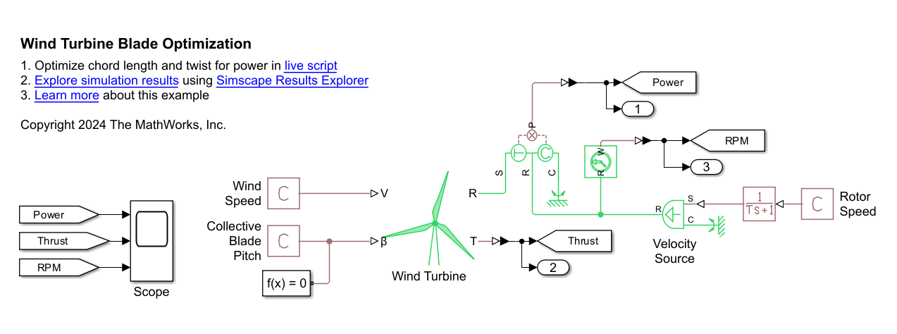
Wind Turbine Blade Optimization
Adjust the twist and chord length along a wind turbine blade to optimize the power output. It combines a Simscape™ Driveline™ test harness model with the fminsearch optimization function. The wind turbine model uses blade element momentum (BEM) theory, including wake rotation. By putting the test harness into Fast Restart, you can enable rapid optimization iterations. In this case, the optimization increases the power output from 4.3 MW to 5.9 MW. Other products available for performing this type of optimization with Simscape Driveline models include the Optimization Toolbox™ and Simulink® Design Optimization™. These products provide predefined functions to manipulate and analyze blocks using either GUIs or a command line approach.
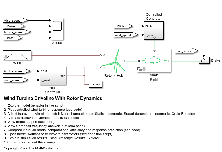
Wind Turbine Driveline with Vibrations
A wind turbine rotor, controller, and flexible drive shaft with transverse vibrations. Click the button below to open the model.
Ports
Inputs
Outputs
Conserving
Parameters
References
[1] Buhl Jr., Marshall L. “New Empirical Relationship between Thrust Coefficient and Induction Factor for the Turbulent Windmill State.” National Renewable Energy Lab (NREL), Golden, CO (United States), No. NREL/TP-500-36834 (2005).
[2] Jain, Palash, Jayant Sirohi, and Christopher Cameron. “Design, Analysis, and Testing of a Passively Deployable Autorotative Decelerator.” Journal of Aircraft 59, no. 1 (January 2022): 272–77. https://doi.org/10.2514/1.C036509.
[3] Jonkman, Jason. “Definition of a 5-MW Reference Wind Turbine for Offshore System Development.” National Renewable Energy Lab (NREL), Golden, CO (United States), No. NREL/TP-500-38060 (2009).
[4] Manwell, J. F., J. G. McGowan, and A. L. Rogers. Wind Energy Explained: Theory, Design and Application. 1st ed. Wiley. 2009. https://doi.org/10.1002/9781119994367.