Aerodynamic Propeller

Libraries:
Simscape /
Driveline /
Engines & Motors
Description
The Aerodynamic Propeller block represents a propeller that converts a rotational mechanical motion into thrust for aerodynamic applications. You can parameterize the propeller by using constants, polynomials, or tabulated data to characterize the thrust and power or coefficients. You can provide tabulated advance velocity data, tabulated advance angle data, or tabulated airfoil lift and drag coefficient data. When you model inertia, the default block parameters represent a 10 kg, two-blade propeller with a 1.5 m diameter.
You can use a physical signal to control the collective blade pitch, cyclic pitch, and transverse flow velocity.
This terminology is helpful for understanding the block:
Advance velocity is the speed of the flow through the propeller, Va.
Advance ratio is the speed of the flow through the propeller with respect to the propeller tip angular speed expressed as a ratio. The block uses this to determine kT and kP when you set Parameterization to
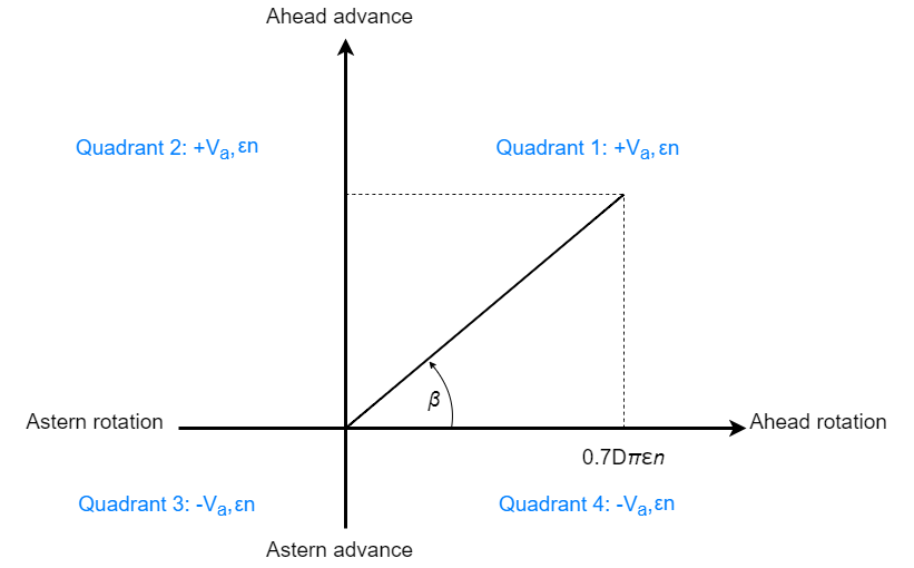
Polynomial fitorTabulated data for advance ratio.Advance angle is the angular location of the propeller operational conditions on a four quadrant plot. The block uses this to determine CT and CQ when you set Parameterization to
Tabulated data for advance ratio.Quadrant is the relative two-dimensional location of the propeller operating condition where the vertical axis is Va and the horizontal axis is ω.
Pitch angle is the angle between the plane of the blade rotation and the chord line of the blade.
The block equations refer to these quantities:
T is the propeller thrust.
Q is the propeller torque.
ρ is the fluid density. You can specify the fluid density using the Density parameter or the Rho port.
θ is the pitch angle.
D is the Propeller diameter parameter.
ω is the propeller angular speed input at port R. For more information about using angular units in Simscape™, see Angular Units.
n is the propeller angular speed in revolutions per second, which consistently nondimensionalizes the power and thrust. The block defines ω = 2πn.
nThr is the Rotational speed threshold parameter.
ε is the Propeller direction parameter.
kT is the thrust coefficient with respect to the propeller rotational speed.
kP is the power coefficient with respect to the propeller rotational speed.
pkT is the polynomial thrust coefficient vector or 2-D matrix.
pkP is the polynomial power coefficient vector or 2-D matrix.
CT is the thrust coefficient with respect to the relative advance velocity.
CQ is the torque coefficient with respect to the relative advance velocity.
kThr is the Saturation threshold for nondimensional coefficients parameter.
J is the advance ratio.
Va is the advance velocity. Specify the advance velocity using the Va port.
VR is the relative advance velocity at a blade section at 70% of the blade radius.
η is the efficiency.
C*T is the thrust coefficient based on the blade relative advance velocity at 70% blade radius.
C*T,TLU is the reference thrust coefficient vector or 2-D matrix.
C*Q is the torque coefficient based on the blade relative advance velocity at 70% blade radius.
C*Q,TLU is the reference torque coefficient vector or 2-D matrix.
β is the advance angle.
βTLU is the reference advance angle.
Parameterizations
The propeller performance depends on the thrust and power coefficients. The Parameterization parameter gives you different options to control these coefficients. The propeller output depends on the quadrant where the propeller operates. The block defines the four quadrants as:
First quadrant: +Va, +n
Second quadrant: +Va, -n
Third quadrant: -Va, -n
Fourth quadrant: -Va, +n
The figure shows a visual representation of the quadrants.
When you set Parameterization to
Constant coefficients, you specify the thrust and
power coefficients directly. Otherwise, the block computes these coefficients
depending on the Parameterization setting.
When you set Parameterization to Polynomial
fit or Tabulated data for advance
ratio, the block uses the advance ratio, J.
The block uses a numerically smoothed version of the fundamental thrust and
power equations such that
The block defines the advance ratio as
where the angular speed threshold nThr linearizes the propeller rotational speed, n, for smoothing.
When you set Parameterization to:
Polynomial fit— kT and kP vary with time according to the values you specify for the polynomial coefficient parameters. The block saturates J to be between 0 and the first positive root of the polynomial and restricts kT and kP to always be positive. The block calculates the thrust and power coefficients aswhere pkT and pkP represent the polynomial coefficients.
Tabulated data for advance ratio— You specify tabulated values for kT and kP for given values of J or J and θ, depending on the Blade pitch type parameter.
When Efficiency sensor is on, the block calculates the efficiency as
When you set Parameterization to Tabulated data for
advance angle, the block uses thrust and power coefficients
with respect to relative advance angle. The block defines the advance angle as
where β is the cyclic pitch. You must ensure that the coefficient extrapolation and cycle wrapping occur as expected. The block defines the thrust and torque coefficients for relative advance velocity as
where VR is the relative advance velocity at a blade section at 70% of the blade radius, such that
Rearranging the coefficient equations yields the block equations for thrust and torque with respect to relative advance velocity:
When you clear Enable collective pitch control, the block calculates the thrust and torque coefficients as
The basis of the propeller efficiency is the fundamental relationship
When Efficiency sensor is on, the block calculates the smoothed efficiency as
When you set Parameterization to Tabulated data for
airfoil lift and drag coefficients, you can parameterize the
lift and drag coefficients and the airfoil geometry for a given blade element.
The block treats the propeller as a continuous disc. Conservation of momentum
applies to the air that crosses the disc when the block calculates the induced
velocity, vi. The block uses the
induced velocity to find the magnitude and direction of the total flow velocity
at a vector of radial locations along the blade, which it then uses to find lift
and drag based on the lift and drag coefficient lookup tables. These quantities
are specific to this parameterization:
TMT — Thrust calculated by momentum theory
vi — Flow velocity induced by the motion of the propeller
vinflow — Freestream inflow velocity of the air that the propeller experiences
vax — Axial velocity at the blade location
vh — Theoretical hover-induced velocity
λ — Non-dimensionalized vax
g(λ) — Function the block uses for inflow
TBET — Thrust as calculated by blade element theory
QBET — Torque as calculated by blade element theory
Nblades — Number of propeller blades
r — Discrete blade element location as defined by the Nondimensional radial location vector, r parameter, which the block interpolates to find y
c — Chord length for at a position along the blade, where the length is non-dimensionalized such that c = Geometric chord length/D
e — Nondimensional location of the root cutout as given by the first element of the Nondimensional radial location vector, r parameter
vr(y) — Tangential velocity as a function of y
Cl,Cd — Element-wise coefficients of the lift and drag, respectively
ϕ(y) — Inflow angle at a given point along the blade
The block uses momentum theory to define a smoothed thrust equation such that
where the block implicitly solves for TMT and vi. The figure shows how the block considers translational motion. The larger area enclosed in the dotted line includes internal mass. The smaller area does not.
This figure shows how the block considers rotational motion. The larger area enclosed in the dotted line includes internal inertia. The smaller area does not.
The block smoothes vax to find vinflow, which allows for transitions between forward and astern flow such that
The block interpolates the values from the Nondimensional radial location vector, r parameter to find y. Then the block interpolates the lift and drag coefficients to find Cl(y) and Cd(y) based upon the tabulated angle of attack and lift and drag coefficients. The block uses blade element theory to calculate the thrust and torque such that
The block performs this integration across the each discrete blade element. The block discretizes y according to the specification in the Number of blade elements parameter. This figure summarizes the directions of forces and torques with respect to the ground.
Controls
By default, the block constrains the blade pitch and collective cyclic pitch to zero. You can optionally control one or both of these characteristics by using physical signals. When you control the cyclic, you also provide a physical signal for transverse flow.
Collective pitch controls the overall lift of the aircraft by changing the pitch angle of all the rotor blades simultaneously and uniformly.
When you set Parameterization to Tabulated
data for advance angle and select Enable collective
pitch control, you can parameterize the propeller over a range
of pitch angles, θ. You must specify θ as
a vector in the Pitch angle vector,θ parameter,
where each element corresponds to a row in both the
kT and
kP arrays. The block
calculates the thrust and power coefficients as
Cyclic pitch controls the roll and pitch of the aircraft by changing the pitch angle of
the rotor blades cyclically as they rotate. When you set
Parameterization to Tabulated data for
airfoil lift and drag coefficients and select
Enable transverse flow and cyclic controls, the block
takes the lateral and longitudinal cyclic pitch as physical signals from ports
θ_1c and θ_1s, respectively. You provide the
airstream angle as a physical signal at port ξ. The block outputs
the lateral and longitudinal forces and moments to ports Fx,
Fy, Mx, and My.
The block accounts for the inflow angle, ξ, along the azimuthal location, ψ, when calculating thrust and torque, such that
After the block calculates the values of Cl(y) and Cd(y), it uses the blade forces to calculate the blade element theory quantities, such that
where Fi,Normal and Fi,Planar are the normal and planar forces on the given blade, iblade. The calculates these forces by using the equations
The block then integrates along y and discretizes the propeller according to the azimuthal location, which it integrates to compute the effects over the period of one revolution, such that
where the block normalizes the output over 2π.
Use the Number of azimuthal locations parameter to specify the number of locations along the azimuth where the block integrates the forces and moments.
Inertia
You can optionally include translational and rotational propeller inertia. To simulate
inertia, set Rotational connections or Translational
connections to Conserving, and select
Model inertia. When you select Model
inertia and set Rotational connections to
Conserving, set the initial rotational velocity or
torque on the shaft in the Initial Targets section, or set an
algebraically linked variable to high priority to initialize the rotational inertia.
When you select Model inertia and set Translational
connections to Conserving, set the initial
translational velocity or thrust in the Initial Targets
section, or set an algebraically linked variable to high priority to initialize the
translational mass.
Note
For rotational conserving connections, the block logs
Q, the aerodynamic torque, and
Inertia.t.
For translational conserving connections, the block logs
thrust, the aerodynamic thrust, and
mass.f.
You can use an Ideal Torque Sensor or Ideal Force Sensor blocks to log the sum of the inertia and the aerodynamic torque or force, respectively.
Assumptions and Limitations
The block treats the fluid velocity as quasi-steady in time. Fluid flows uniformly over the propeller.
The block only accounts for axial flow across the propeller.
When you set Parameterization to
Polynomial fit, the block assumes that the propeller power and thrust coefficients are symmetric with the first quadrant.When you set Parameterization to
Tabulated data for advance
						ratio
, the block assumes the power and thrust coefficients are identical in the first and third quadrants and the second and fourth quadrants. If all elements of J are positive, then the block assumes the coefficients in all quadrants are symmetric with the first quadrant.When you set Parameterization to
Tabulated data for
						advance angle
, the block removes the sign from Va. To attain negative thrusts and torques, you must include the signs in the values of CT and CQ.
Variables
To set the priority and initial target values for the block variables prior to simulation, use the Initial Targets section in the block dialog box or Property Inspector. For more information, see Set Priority and Initial Target for Block Variables.
Nominal values provide a way to specify the expected magnitude of a variable in a model. Using system scaling based on nominal values increases the simulation robustness. Nominal values can come from different sources, one of which is the Nominal Values section in the block dialog box or Property Inspector. For more information, see Modify Nominal Values for a Block Variable.
Examples
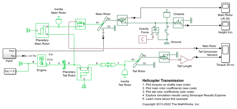
Helicopter Transmission
A fixed helicopter transmission testbed. The gasoline engine provides power that is sent to the main and tail rotors through planetary gearsets. The main rotor shaft is considered rigid, and flexibility is modeled in the longer, thinner tail rotor shaft. Blade pitch angle is set directly via a physical signal. Swash plate dynamics can be added using the appropriate blocks in Simscape™ Fluids™. The engine stalls after six seconds, but lift is maintained for some time through the unidirectional clutch. This scheme also allows autorotation of the main rotor in a descending helicopter.