SI Combustion Cylinder
Libraries:
Simscape /
Driveline /
Engines & Motors /
Engine Subcomponents
Description
The SI Combustion Cylinder block represents the crank-angle-resolved, instantaneous pressure production dynamics of a spark-ignited, four-stroke internal combustion engine cylinder. You can use this block as a subcomponent in a composite internal combustion engine block, such as the Spark Ignition Engine block. The block computes the instantaneous cylinder pressure and also provides optional outputs to collect additional information. To obtain the instantaneous torque, connect one or more of these blocks with the Crankshaft block. This page uses these common industry abbreviations:
TDC — Top dead center
BDC — Bottom dead center
IVO — Intake valve open
IVC — Intake valve close
EVO — Exhaust valve open
EVC — Exhaust valve close
VVT — Variable valve timing
Equations
The block depends on the angular position of the crank, θ, where TDC is 0°, and the crank position can range from 0° to 720°. Using this definition, 0° is the intake TDC, and 360° is the combustion TDC. The block calculates the instantaneous cylinder volume as a function of the crank position such that
where:
Vcl is the clearance volume.
Vdispl is the displacement volume, which the block finds from the Bore and Stroke parameters.
l is the Connecting-rod length parameter.
a is the crank radius.
The block calculates Vcl as
where rc is the Compression ratio parameter. The time derivative of V(θ) scales the instantaneous power that the cylinder generates, Q(θ), such that
where Pcyl(θ) is the cylinder pressure as a function of the crank position, and Pamb is the Ambient pressure parameter. The block formulation to compute Pcyl(θ) depends on which part of the stroke cycle is active in the cylinder.
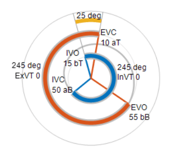
These plots show the stroke status with respect to the crank position. The spiral line represents the crank rotation. The spiral begins at IVO and ends at EVC. Depending on timing, there may be overlapping times where both the intake and exhaust valves have the same condition. Positive overlap happens when IVO occurs before EVC. Negative overlap happens when EVC occurs before IVO. Using this definition, there can be six unique modes depending on whether the overlap occurs before, during, or after TDC. The block approximates these modes.

This plot shows a typical valve timing scenario where IVO occurs 15 degrees before TDC, and IVC occurs 50 degrees after BDC. EVO occurs at 55 degrees before BDC, and EVC occurs at 10 degrees after TDC. Note the 25 degrees of positive overlap where the intake valves open before the exhaust valves close. The table demonstrates the six valve overlap modes.
| Before TDC | During TDC | After TDC | |
|---|---|---|---|
| Positive Overlap |
|
|
|
| Negative Overlap |
|
|
|
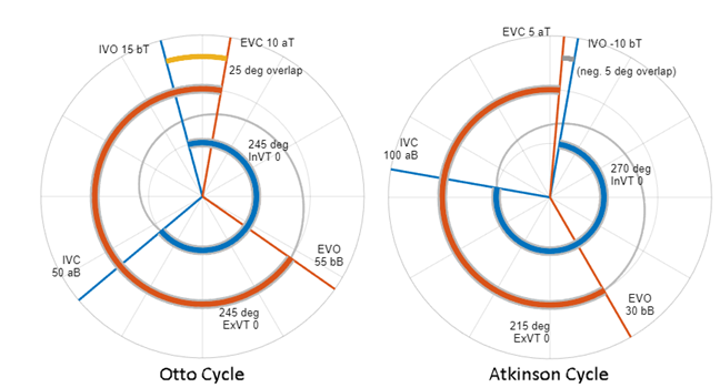
You adjust the parameters in the Valves section to represent either an Otto cycle or an Atkinson cycle. Gasoline engines typically use the Otto cycle due to its balance of power and efficiency. Hybrid engines and some modern gasoline engines use the Atkinson cycle to enhance fuel efficiency by sacrificing power output. Using Atkinson cycle timings for either the Spark Ignition Engine or SI Combustion Cylinder blocks results in:
A smaller effective compression ratio and larger expansion ratio
Improved fuel efficiency
Reduced torque and power for a given displacement
The figure shows a comparison of typical timings for the Otto cycle and the Atkinson cycle :

During normal operation, the engine cylinders require a minimum engine speed to maintain stable combustion. However, during transient operations, such as using the starter motor to turn the crank, the cylinder completes stroke cycles without attaining stable combustion. The block takes these slow engine speed interactions into account such that the block considers 18 possible modes. These are the slow engine operation modes:
Slow Intake
Slow Compression-Expansion
Slow Exhaust
Slow Positive Overlap Before TDC
Slow Positive Overlap During TDC
Slow Positive Overlap After TDC
Slow Negative Overlap Before TDC
Slow Negative Overlap During TDC
Slow Negative Overlap After TDC
These are the regular engine operation modes:
Intake
Compression-Expansion
Exhaust
Positive Overlap Before TDC
Positive Overlap During TDC
Positive Overlap After TDC
Negative Overlap Before TDC
Negative Overlap During TDC
Negative Overlap After TDC
The block gives each discrete mode a transition constraint by using the mode chart feature. The table shows which transitions the block allows.
| Mode Transition | Allowed Modes |
|---|---|
| Slow ↣ Slow |
|
| Slow ↣ Regular |
|
| Regular ↣ Regular |
|
| Regular ↣ Slow |
|
The flow chart in the figure visually depicts how the block steps through the modes.
Mode Transition Flowchart

The block captures the effect of the valve timings on the effective compression ratio and considers the effect of IVC much later than BDC which can reduce the amount of air charged in the combustion cylinder. However, the block ignores internal exhaust gas recirculation.
Assumptions and Limitations
The block ignores knocking and other combustion instabilities.
The block ignores internal and external exhaust gas recirculation.
Examples
Ports
Input
Output
Parameters
Version History
Introduced in R2022aSee Also
Spark Ignition Engine | Crankshaft | Ignition Trigger | Air Intake | Exhaust Manifold Thermal


