Sonar Equation Calculator
Estimate maximum range, SNR, transmission loss and source level of a sonar system
Description
The Sonar Equation Calculator app solves the basic sonar equation for monostatic sonar systems. The sonar equation relates transmission loss (or target range), source level, directivity, noise level, target strength, and signal SNR. You can solve for one of these quantities in terms of the others. Using this app, you can:
Calculate the received SNR value from transmission loss (or equivalently, target range), source level, and noise level.
Solve for transmission loss from sonar source level of the sonar, specified received SNR, and array directivity.
Solve for target range from sonar source level of the sonar, specified received SNR, and array directivity.
Calculate required source level from target range, source level, and received SNR.

Open the Sonar Equation Calculator App
MATLAB® Toolstrip: On the Apps tab, under Signal Processing and Communications, click the app icon.
MATLAB command line: Enter
sonarEquationCalculator.
Examples
Compute the maximum detection range of an active monostatic sonar designed to achieve an SNR of at least 10 dB. The operating frequency is 5 kHz, and the source level is 180 dB. Assume that the noise level is 73 dB, the receiver directivity is 20 dB, and the target strength is 10 dB.
Set Calculation to
Target Range.Set Mode to
Active.Set Noise Level to
73dB//1μPa.Set receiver Directivity index to
20dB.Set Target Strength to
10dB.Set Frequency to
5kHz.Set channel Depth to
100m.Set Source Level to
180dB//1μPa.Set required SNR to
10dB.

The maximum target range is 14.61 km.
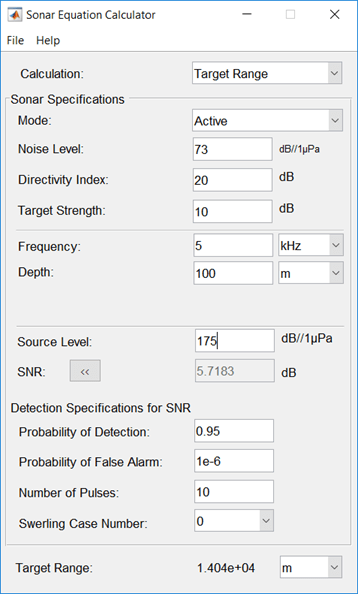
Use multiple pulses to reduce the source level while maintaining the same maximum target range.
Start with the values set in the Maximum Detection Range of Active Sonar example.
Click the arrows to the right of the SNR label to access the Detection Specifications for SNR options.
Set Probability of Detection to
0.95.Set Probability of False Alarm to
1e-6.Set Number of Pulses to
10.Reduce Source Level to
175.Set the Swerling Case Number to
0assuming a nonfluctuating target.

The maximum detection range is 14.81 km, approximately the same as in the previous example, but the source level is reduced by 5 dB.
Compute the source level for an active monostatic sonar with a received SNR of 15 dB. The target range is 5 km and the target strength is 25 dB. Assume a 5-kHz sonar frequency.
Set Calculation to
Source Level.Set Mode to
Active.Set Noise Level to
75.Set receiver Directivity index to
20dB.Set Target Strength to
25.Click the arrows to the right of the Transmission Loss label to access the Calculation of Transmission Loss options.
Set the Range to
10.0km.Set the Frequency to
5kHz.Set the Depth to
200m.Set SNR to
15dB.

The required source level is 171.6 dB//1 μPa.
Compute the received SNR for a passive sonar with a source level of 140 db//1 μPa for a source 10.0 km away. Assume a 3-kHz sonar frequency.
Set Calculation to
SNR.Set Mode to
Passive.Set Noise Level to
75.Set receiver Directivity index to
20dB.Click the arrows to the right of the Transmission Loss label to access the Calculation of Transmission Loss options.
Set Range to
10.0km.Set Frequency to
3kHz.Set Depth to
200m.Set Source Level to
140dB//1 μPa.

The received SNR is 23.16 dB.
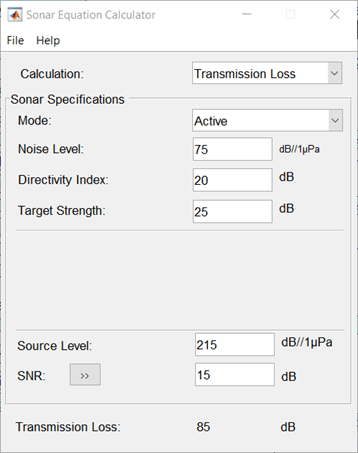
Compute the transmission loss for an active sonar that results in an SNR of 15 dB. The source level is 215 dB//1 μPa. Assume that the noise level is 75 dB//1 μPa, the receiver directivity is 20 dB, and the target strength is 10 dB.
Set Calculation to
Transmission Loss.Set Mode to
Active.Set Noise Level to
75dB.Set receiver Directivity index to
20dB.Set Target Strength to
25dB.Set Source Level to
215dB.Set required SNR to
15dB.

The transmission loss is 85 dB.
Parameters
Select the type of calculation:
Target Range-— solves for the maximum target range based on source level of the sonar and required received SNR.Transmission Loss-— computes the required transmit power from known target range and required received SNR.Source Level-— computes the source level from the range or transmission loss, and received SNR.SNR-— calculates the received SNR value based on known range and transmit power.
Specify whether the sonar is operating in active mode or passive mode. Active mode means that a signal is transmitted from a source, reflects off a target, and returns to the receiver which is collocated with the source. Active mode requires the specification of the reflector target strength. Passive mode means that the signal is transmitted from a source to a receiver along a direct path.
Noise level at sonar receiver, specified as a scalar. Units are dB//1μP.
Directivity index of receive array or element, specified as a scalar. Units are dB.
Target strength of reflector, specified as a scalar. Units are dB//1m2.
Dependencies
To enable this parameter, set the Mode parameter
to Active.
Sound frequency, specified as a positive scalar. Default units are in kHz.
You can also select Hz,
kHz, or
MHz.
Water channel depth. Default units are meters. You can select units in
m, km,
mi, or nmi.
Source level of sonar transmitter, specified as a scalar. Units are dB//1 μP.
Specify an SNR value, or calculate an SNR value using the Detection Specifications for SNR options. You can calculate the SNR required to achieve a particular probability of detection and probability of false alarm using the Shnidman equation. To calculate the SNR value:
Click the arrows to the right of the SNR label to access the Detection Specifications for SNR options.
Enter values for Probability of Detection, Probability of False Alarm, Number of Pulses, and Swerling Case Number.
Dependencies
To enable this parameter, set Calculation to
Target Range, Transmission
Loss, or Source Level.
Specify the detection probability used to estimate SNR using the Shnidman equation.
Dependencies
To enable this parameter, set Calculation to
Target Range, Transmission
Loss, or Source Level, and
select the Detection Specifications for SNR options
for the SNR parameter.
Specify the false alarm probability used to estimate SNR using the Shnidman equation.
Dependencies
To enable this parameter, set Calculation to
Target Range, Transmission
Loss, or Source Level, and
access the Detection Specifications for SNR options
for the SNR parameter.
Specify the number of pulses. You can specify multiple pulses for noncoherent integration in the Shnidman equation.
Dependencies
To enable this parameter, set Calculation to
Target Range, Transmission
Loss, or Source Level, and
select the Detection Specifications for SNR options
for the SNR parameter.
Specify the Swerling case number used to estimate SNR using the Shnidman equation. Swerling numbers characterize the detection problem for fluctuating pulses in terms of:
a decorrelation model for the received pulses.
the distribution of scatterers affecting the probability density function (pdf) of the target radar cross section (RCS).
The Swerling cases include two decorrelation models (scan-to-scan or pulse-to-pulse) and two radar cross section pdfs (based on the presence or absence of a dominant scatterer):
0– Nonfluctuating pulses.1– Scan-to-scan decorrelation: Several randomly distributed scatterers with no dominant scatterer described by a Rayleigh/exponential PDF.2– Pulse-to-pulse decorrelation: Several randomly distributed scatterers with no dominant scatterer described by a Rayleigh/exponential PDF.3– Scan-to-scan decorrelation: Several scatterers with one dominant scatterer described by a chi-square PDF with 4 degrees of freedom.4– Pulse-to-pulse decorrelation: Several scatterers with one dominant scatterer described by a chi-square PDF with 4 degrees of freedom.
Dependencies
To enable this parameter, set Calculation to
Target Range, Transmission
Loss, or Source Level, and
select the Detection Specifications for SNR options
for the SNR parameter.
Transmission loss in channel, specified as a scalar. Units are dB. For passive sonar modeling, specify a one-way transmission loss. For active sonar modeling, specify a two-way transmission loss. You can specify a transmission loss value, or calculate transmission loss using the Calculation of Transmission Loss options.
To calculate transmission loss:
Click the arrows to the right of the Transmission Loss label to access the Calculation of Transmission Loss menu.
Enter values for Target Range, Frequency, and Depth.
Dependencies
To enable this parameter, set Calculation to
Source Level or
SNR.
Target range, specified as a positive scalar. When
Mode is Passive, target
range is from source to receiver. When Mode is
Active, target range is from source to
reflecting target. Default units are in meters. You can also select
km, mi, or
nmi.
Dependencies
To enable this parameter, set the Calculation
parameter to Source Level or
SNR and click the arrow next to
Calculation of Transmission Loss.
Signal frequency, specified as a positive scalar. Default units are in
kHz. You can also select Hz,
kHz, and
MHz.
Dependencies
To enable this parameter, set Calculation to
Source Level or
SNR and click the arrow next to
Calculation of Transmission Loss.
Channel depth, specified as a positive scalar. Default units are in
meters. You can also select km,
mi, and
nmi.
Dependencies
To enable this parameter, set the Calculation
parameter to Source Level or
SNR and click the arrow next to
Calculation of Transmission Loss.
Version History
Introduced in R2017b
MATLAB Command
You clicked a link that corresponds to this MATLAB command:
Run the command by entering it in the MATLAB Command Window. Web browsers do not support MATLAB commands.
Select a Web Site
Choose a web site to get translated content where available and see local events and offers. Based on your location, we recommend that you select: .
You can also select a web site from the following list
How to Get Best Site Performance
Select the China site (in Chinese or English) for best site performance. Other MathWorks country sites are not optimized for visits from your location.
Americas
- América Latina (Español)
- Canada (English)
- United States (English)
Europe
- Belgium (English)
- Denmark (English)
- Deutschland (Deutsch)
- España (Español)
- Finland (English)
- France (Français)
- Ireland (English)
- Italia (Italiano)
- Luxembourg (English)
- Netherlands (English)
- Norway (English)
- Österreich (Deutsch)
- Portugal (English)
- Sweden (English)
- Switzerland
- United Kingdom (English)