Model and Control Autonomous Vehicle in Offroad Scenario
In the three preceding examples you learned how to process terrain data, create global planners, and developed a local optimization-based path follower which allow a non-holonomic vehicle to navigate in an offroad setting, specifically an open-pit mine.
Graph-Based Route Planner
The first example showed how to convert 3D digital elevation data to a graph-based road network. This allowed you to represent regions in the mine which exhibit some "structure" (e.g. roads) inside a navGraph for use as a global "route" planner:

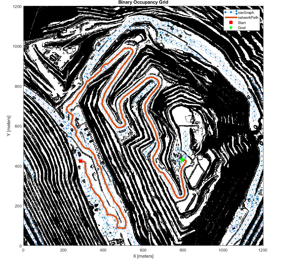
Terrain-Aware Planners
The second example developed two planners which simply operate in the SE2-space and can be used to form short connections through free space while adhering to your vehicle's non-holonomic constraints. The first of which was the "OnrampPlanner", which attempts to connect an SE2 start location to any edges attached to the closest node in the route-planner:
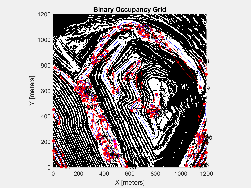
The second planner developed using plannerHybridAStar, which utilizes a custom TransitionCostFcn to penalize motions that move along steep gradients. This planner can always be used, but due to the comparatively large computation costs, it will be used in a fallback capacity when the OnrampPlanner is unable to produce paths to/from the road-network, or when the vehicle needs to replan while path-following.
Path Following with Obstacle Avoidance
In the final example, you developed a controller which attempts to follow a reference path while avoiding obstacles using controllerTEB. This example separated the controller properties into two categories - those that one might want to tune during runtime, and those that should be fixed during simulation, either because they are physical properties of your vehicle, or because they must be fixed at compile-time to support codegen:
[tuneableTEBParams,fixedTEBParams] = exampleHelperTEBParams

tuneableTEBParams =

  struct with fields:

           LookaheadTime: 6
    ObstacleSafetyMargin: 1
             CostWeights: [1×1 struct]
        MinTurningRadius: 17.2000
             MaxVelocity: [16 0.9302]
         MaxAcceleration: [0.6000 0.1000]
      MaxReverseVelocity: 8


fixedTEBParams =

  struct with fields:

                Length: 6.5000
                 Width: 5.7600
          NumIteration: 3
    ReferenceDeltaTime: 0.2000
      RobotInformation: [1×1 struct]
Creating Autonomous Planning Stack
Begin by generating all necessary parameters and terrain data:
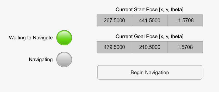
exampleHelperCreateBehaviorModelInputs

% Define the initial start pose of the vehicle in the scene:
start = [267.5 441.5 -pi/2];
goal  = [479.5  210.5 pi/2];

% Set a new goal state to begin planning framework
maxElementPerEdge= 25;
To simulate the vehicle, open the top-level Simulink model:
% Open the model
model = 'IntegratedBehaviorModule';
open_system(model);

Here you can see a set of subsystems housing the modules developed in the previous three examples and a Stateflow chart responsible for transitioning between the vehicle's different operational states:
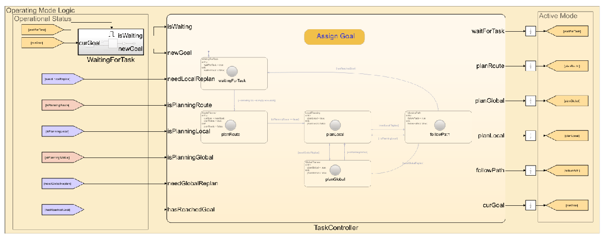
The table below establishes a rough correspondence between each operational state and their associated feature/example:
Operational State | Subsystem | Logic/Description | Modules/Functionality | Source Example |
|---|---|---|---|---|
| WaitingForTask | Waits for the user to provide a | n/a | n/a |
| GlobalPlanner/RoutePlanner | Whenever a new | Constructs the Once found, the |
|
| GlobalPlanner/TerrainPlanner | In this example, the 1) As a backup planner in the event that the 2) As a planner used to transition the vehicle from the end of the Similar to the | The Similar to the |
|
| PathFollower/LocalPlanner | This subsystem takes in the reference path produced by either the This command sequence is fowarded to the | This subsystem contains two modules: 1) A block responsible for extracting a local map from the global map 2) The local optimization-based The agent forwards time-stamped control sequences and optimized path to the |
|
| PathFollower/Controller | The The controller is also responsible for determining whether a new local plan should be requested, and checks whether the vehicle has either reached the end of the reference-path, or reached the goal. If the agent has reached the end of the reference path, which corresponds to the | The current subsystem simply indexes into the command-sequence produced by the This functionality was originally developed alongside the In complex/robust systems, it may be desireable to implement some feedback control to minimizing error between the vehicle's current location ( |
|
Simulating Autonomous Vehicle
% Visualize the map. Blocks inside the model will update the figure as the
% simulation runs if you have enabled "visualization" on the block masks
% within the model.
f = figure;
f.Visible = "on";
binMap = binaryOccupancyMap(~imSlope);
show(binMap);

To begin the simulation, you can either:
1) Click run to start the simulation, and subsequently update the "goal" by using the "Assign Goal" button on the TaskController block. In this workflow, the vehicle will remain in the "waiting" state until the goal has been provided:

2) Alternatively, you may initialize the goal value and start the simulation programmatically, which will begin the planning and path following as soon as the simulation begins:
% Set an initial goal for the simulation
set_param([model '/WaitingForTask/newGoalBlock'],'Value','goal');

% Begin the simulation
set_param(model,'SimulationCommand','start');
Results and Discussion
In this example you learned how to integrate different planning subsystems together using Simulink and Stateflow to create a navigation stack for an autonomous vehicle in offroad terrain. The individual modules were developed and tested incrementally using MATLAB, and then exposed to Simulink via MATLAB Function blocks and Stateflow.
Related Topics
You can also select a web site from the following list:
Americas
- América Latina (Español)
- Canada (English)
- United States (English)
Europe
- Belgium (English)
- Denmark (English)
- Deutschland (Deutsch)
- España (Español)
- Finland (English)
- France (Français)
- Ireland (English)
- Italia (Italiano)
- Luxembourg (English)
- Netherlands (English)
- Norway (English)
- Österreich (Deutsch)
- Portugal (English)
- Sweden (English)
- Switzerland
- United Kingdom (English)