Model Comparator with Hysteresis Using Operational Amplifier
This example shows how to model an analog comparator with hysteresis using the Operational Amplifier block from Mixed-Signal Blockset™.
Comparator
An analog comparator is used to compare two analog signals and output a digital signal that indicates which signal has a higher/lower magnitude. An example would be to detect an undervoltage condition in which case the signal to be compared is applied to the negative input terminal of the comparator. When Vin is below Vref, the comparator output is high indicating an undervoltage condition. A high-gain operational amplifier is generally used as an analog comparator.
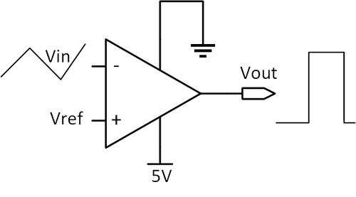
Need for Hysteresis
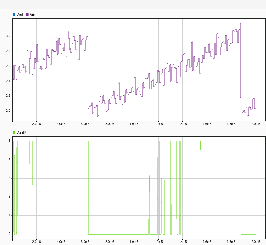
Any noise on the input signals results in multiple transitions at the output as shown below. This is not ideal since the block that expects the comparator output might oscillate between states.
A comparator with hysteresis is used to avoid the issue of multiple transitions in the presence of noise. Hysteresis sets different thresholds for low-to-high and high-to-low transitions using positive feedback. The reference design explained in "Comparator with Hysteresis Reference Design" by Texas Instruments® [1] is modeled in this example. The reference design uses the component TLV3201, a comparator from Texas Instruments. The circuit schematic of the reference design is shown below. Positive feedback using resistive network is used to generate two different thresholds, thereby providing hysteresis behavior. The signal is connected to the negative input terminal and hence the output goes high when the signal is below threshold (VH or VL). The resistor Rh sets the hysteresis level.
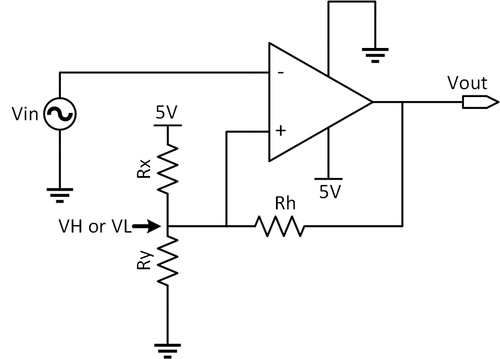
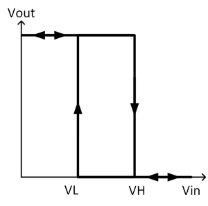
When the comparator output is at logic high (5V), Rh is in parallel with Rx, raising the threshold voltage (VH) to 2.7V. The input signal must be greater than VH=2.7V for the output to transition to logic low (0V). When the comparator output is at logic low (0V), Rh is in parallel with Ry, reducing the threshold voltage to 2.3V. In this case the input signal must be smaller than VL=2.3V for the output to transition to logic high (5V).
Comparator with Hysteresis Using Simulink Blocks
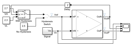
The comparator explained in the previous section can be modelled in Simulink using the Operational Amplifier block. To model the circuit, you can use the Linear Circuit Wizard block.
Although the exact schematic cannot be modeled in Simulink using the Operational Amplifier block, the behavior can be simulated using a few simple blocks. The comparator circuit used in the previous sections has a threshold of 2.7V (VH) when the output is high and a threshold of 2.3V (VL) when the output is low. To simplify modeling the behavior of the resistive feedback network, you can use a switch to set the threshold value based on the state of terminal "OutputPlus" of the Operational Amplifier. The switch selects 2.3V as the threshold when OutputPlus is close to 5V and 2.7V as the threshold when OutputPlus is 0V. You need to use a delay block to prevent algebraic loop issues during simulation.
open_system('comparatorExample.slx')
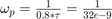
The Operational Amplifier block is configured so that "Supply rail high" = 5V and "Supply rail low" = 0V. The transfer function poles are set such that the Operational Amplifier has a single pole response providing a propagation delay close to 40ns, which is the propagation delay of TLV3201 comparator from Texas Instruments. The dominant pole was calculated using 80% of comparator delay ( ) and taking the inverse as shown below:
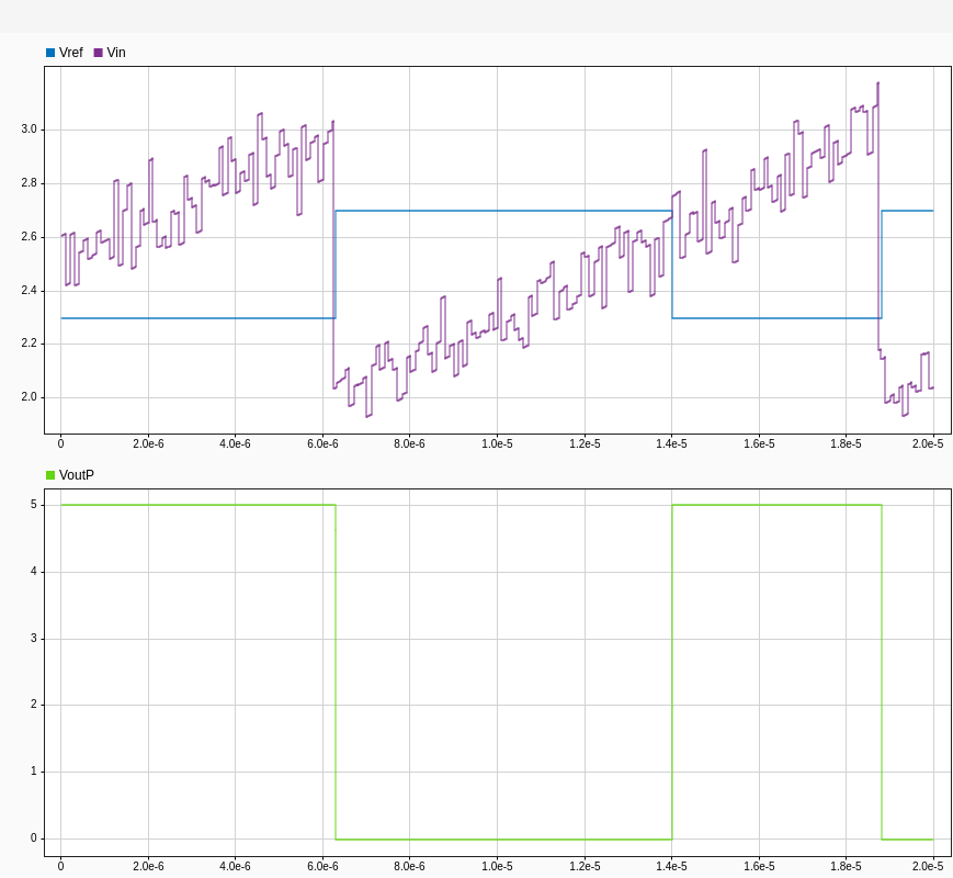
The transfer function zero is set close to the non-dominant pole so that it cancels out the non-dominant pole. Simulation results show the expected behavior for a comparator with hysteresis, and it can be observed that there are no multiple transitions even in the presence of noise. You can toggle the manual switch called "Hysteresis Switch" to check the circuit behavior with and without hysteresis.
Reference
Art Kay and Timothy Claycomb. "Comparator with Hysteresis Reference Design." https://www.ti.com/lit/ug/tidu020a/tidu020a.pdf