Design Inverting Amplifier
This example shows how to model an inverting amplifier circuit using the Operational Amplifier block and the Linear Circuit wizard block.
Inverting Amplifier
The inverting amplifier circuit contains an op-amp and a feedback network consisting of passive resistors. In this example, the Linear Circuit Wizard block is used to model the feedback network. The Linear Circuit Wizard uses a SPICE netlist describing the feedback stage from the output of the op-amp to its input.
Open the model Inverting_Amplifier attached to this example.
open_system('Inverting_Amplifier');
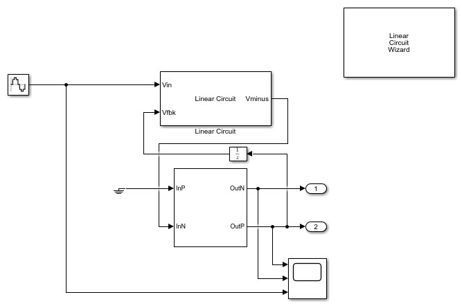
Operational Amplifier
The op-amp used in this example is a double pole circuit defined from the circuit parameters. In this example, the Input offset voltage (V) is set to 0, the Output resistance (Ohms) is set to 80, and the Open loop gain (v/v) is set to 855e3. The Unity Gain Bandwidth (Hz) is 1e8 Hz and the Maximum Tail Current (A) is 100e-6.
Linear Circuit Wizard
The Linear Circuit Wizard block uses a SPICE netlist to generate a linear circuit block. You can specify the SPICE netlist file name and click on the Build/modify block button to create a circuit block that models the SPICE netlist. The netlist attached to this example is InvertingAmplifier.sp.
Operation
The inverting amplifier circuit is designed with an Op-amp and a feedback network consisting of two resistors R2 and R1.
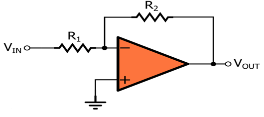
The feedback from Op-amp output to the input terminal is modeled in the attached SPICE file (R2 = 20KOhms, R1 = 2KOhms).
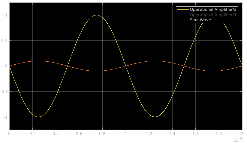
The closed loop gain of the inverting amplifier is -R2/R1, which is equal to -10. The input stimulus applied to this model has a sample rate of 1e-8. The same sample rate is used in the operational amplifier.
An input signal of 0.1V sine wave with 1KHz frequency is provided to the circuit model. The input and corresponding output are seen on the scope.
See Also
You can also select a web site from the following list:
Americas
- América Latina (Español)
- Canada (English)
- United States (English)
Europe
- Belgium (English)
- Denmark (English)
- Deutschland (Deutsch)
- España (Español)
- Finland (English)
- France (Français)
- Ireland (English)
- Italia (Italiano)
- Luxembourg (English)
- Netherlands (English)
- Norway (English)
- Österreich (Deutsch)
- Portugal (English)
- Sweden (English)
- Switzerland
- United Kingdom (English)