Run in Open-Loop and Switch to Closed-Loop
When operating a permanent magnet synchronous motor (PMSM) with a quadrature encoder sensor, we need an initial position to start running the motor. Because we do not have a method to determine the initial position at the beginning (before starting the motor), run the motor using open-loop control and ensure that the quadrature encoder index pulse is read at least once. At the quadrature encoder index pulse, the quadrature encoder sensor resets its position to align with the mechanical angle of the motor. The motor switches from an open-loop run to closed-loop speed control to maintain the reference speed. This step is only applicable for a quadrature encoder sensor (and is not needed for a Hall position sensor). A Hall sensor outputs the initial position of the rotor segment from the Hall signal port inputs.
Follow these steps to implement an open-loop motor run with a transition to closed-loop control:
Copy the
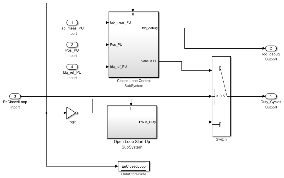
mcb_pmsm_foc_qep_f28379d/Current
                            Control/Control_system
subsystem to your model. This adds the algorithm to run the motor in open-loop. This subsystem switches the control from open-loop to closed-loop if EnClosedLoop input is1. Add an input port EnClosedLoop.Addition of the Open Loop Start-Up subsystem adds the Data Store Read blocks for Enable and SpeedRef. In addition, add the Data Store Memory blocks for Enable, EnClosedLoop, and SpeedRef at the topmost level of the model.
When the open-loop run begins, the sign of SpeedRef (for algorithm details, see the Open Loop Start-Up subsystem) decides the direction of the initial motor run. If SpeedRef is negative, the motor spins in the opposite direction during the open-loop run.
Copy the
mcb_pmsm_foc_qep_f28379d/Current Control/Input
                            Scaling/Calculate Position and Speed
subsystem to your model. This adds theIndexFindersubsystem to your model. When quadrature encoder index pulse is detected for the first time, this subsystem sets theIndexFoundport to1. Add an output port (that is connected to theIndexFoundport) to the Calculate Position and Speed subsystem and rename it toEnClosedLoop.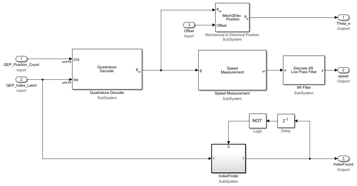
Connect the output port
EnClosedLoopfrom the Input Scaling subsystem to the input portEnClosedLoopin the Control_System subsystem as shown in this figure.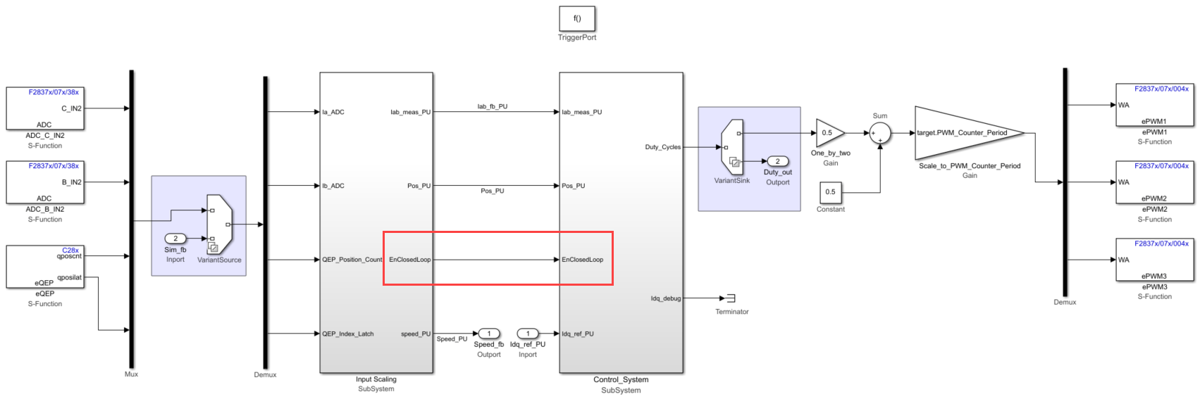
Copy the
mcb_pmsm_foc_qep_f28379d/Speed
                            Control/Speed_Ref_Selector
subsystem to your model and integrate it with the speed controller subsystem. When the closed-loop control begins, this subsystem provides theSpeed_Refoutput signal. For a smooth transition from open-loop to closed-loop, the speed measured is used as the speed reference during the open-loop run. Add a Data Store Write block SpeedRef to thePI_Controller_Speedinput port.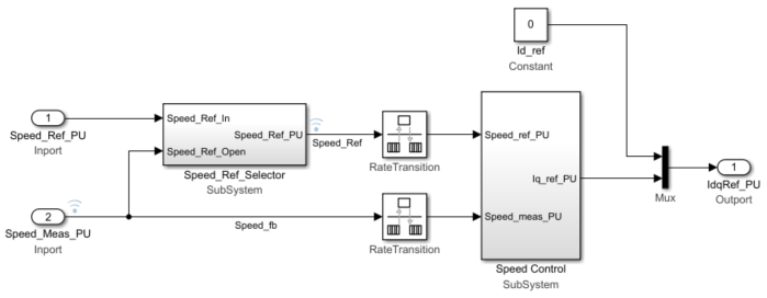
In the plant model, add a step input to simulate the IndexFinder block for simulation. Rename the step input to
Switch to closed loop. See themcb_pmsm_foc_qep_f28379d/Inverter and Motor - Plant Model/Sensor_Measurmentssubsystem to see how the step input switches to closed-loop. Select the step time of0.1and sample time of Ts_motor.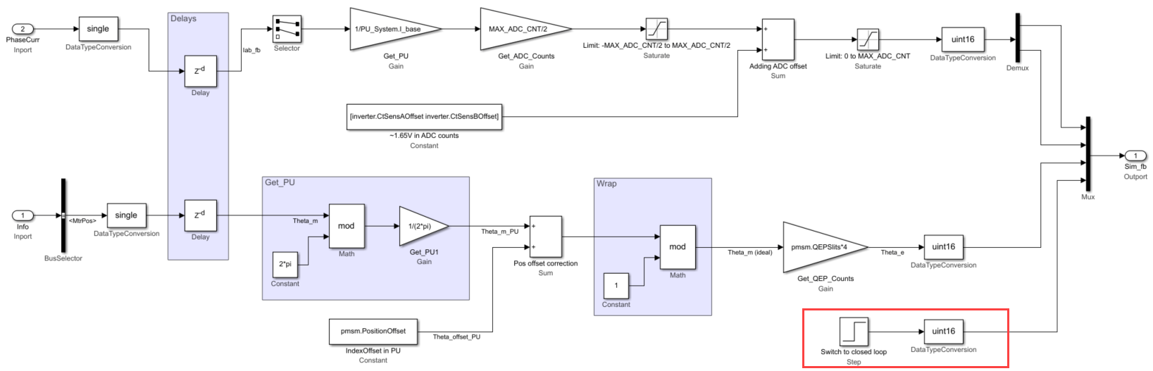
Create Data Store Memory blocks for EnClosedLoop, Enable, and SpeedRef. Enable block is used to reset the PI integrator before running the motor.
Add these default values in the Data Store Memory blocks:
Enable =
1EnClosedLoop =
0SpeedRef =
0.25
The Data Store Memory blocks are used to share data across the subsystem.
Run the simulation and observe the speed reference and the speed feedback signals.