Task Scheduling in Target Hardware
In the example model mcb_pmsm_foc_sim, configuring the current
controller and the speed controller are the two important tasks. The current controller
is scheduled to run after every Ts
(50 µsec for a 20 kHz switching frequency) and
the speed controller runs after every Ts_speed
(10*Ts). The current
controller reads the motor phase currents and position and computes the PWM duty cycle
to run the motor. The speed controller runs the control loop, calculates
Iq reference for the current controller,
and controls the motor speed in the closed-loop.
In the target hardware, the current controller is synchronized with the ADC interrupt
(for every Ts) and the speed controller is
triggered after every Ts_speed
(10*Ts).
This figure shows the event sequence, interrupt trigger, and software execution time for the control algorithm running in the target hardware.
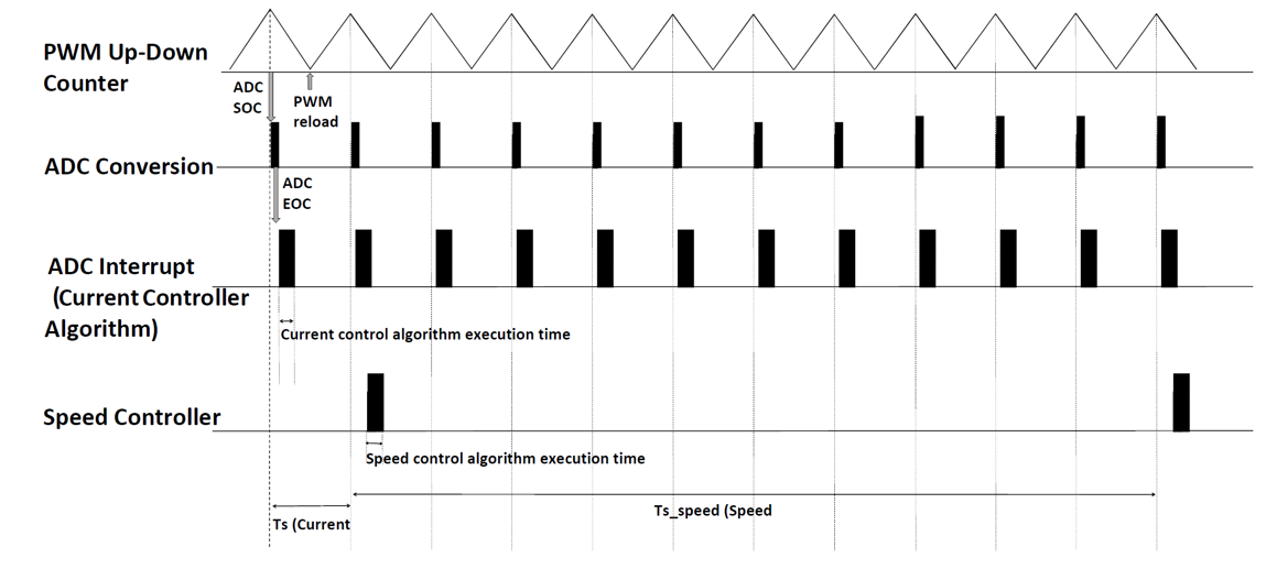
In this figure, the execution times for the current controller and speed controller are not in scale. See the processor datasheet to better understand the functionality of the processor peripherals such as the ADC (analog-to-digital converter) and the PWM (pulse-width modulation).
The model follows this event sequence:
The processor peripheral PWM, which is center-aligned (Up-Down Counter), triggers the start-of-conversion (SOC) event for the ADC module when the PWM counter value equals the PWM period.
The ADC module converts the sampled analog signal into digital counts and triggers the end-of-conversion (EOC) event.
The EOC triggers the ADC interrupt.
The current controller is scheduled to execute with the ADC interrupt.
The speed controller is scheduled to run after every Ts_speed.
You can also use SoC Blockset™ for task scheduling, profiling, and addressing challenges related to ADC-PWM synchronization, controller response, and studying different PWM settings. For details, see Integrate MCU Scheduling and Peripherals in Motor Control Application.