PMSM FeedForward Control
Decouple d-axis and q-axis current to eliminate disturbance
Libraries:
Motor Control Blockset /
Controls /
Control Reference
Description
The PMSM FeedForward Control block decouples d-axis and q-axis current controls and generates the corresponding feedforward voltage gains to enable field-oriented control of a permanent magnet synchronous motor (PMSM).
You can input feedback values of d-axis and q-axis currents and the mechanical speed of the rotor.
The block generates feedforward gains from the specified motor parameters using one of these methods:
Linear model with lumped parameters— Lumped parameters with d-axis and q-axis stator winding inductances and permanent magnet flux linkage.Non-linear model with D,Q-flux linkage LUTs— Nonlinear model with d-axis and q-axis flux linkage lookup tables.Non-linear model with Ld, Lq, and FluxPM LUTs— Nonlinear model with d-axis and q-axis stator winding inductances and permanent magnet flux linkage lookup tables.Input port based Ld, Lq, and FluxPM— d-axis and q-axis stator winding inductances and permanent magnet flux linkage values provided using separate input ports.
In addition, you can use the Vsat input method parameter to configure the block to accept a fixed saturation voltage through the Output saturation (V) parameter or a variable saturation voltage through a separate input port Vsat.
Equations
If you select Per-Unit (PU) in the Input
units parameter, the block scales down the internal parameters to match the
per-unit scale by default. You can also configure the block to convert the inputs to SI
units before performing any computation and convert them back to per-unit values after
calculating the output by using the Allow scaled-down motor parameters with
CodeGen (higher precision with Fixed-Point data type) parameter.
These equations describe how the block computes feedforward gain.
where:
is the number of pole pairs available in the motor.
is the electrical speed corresponding to frequency of stator voltages (rad/s).
and are the d-axis and q-axis stator winding inductances (henries).
and are the d-axis and q-axis currents (amperes).
ψd and ψqare the magnetic fluxes along the d- and q-axes (weber).
ψm is the permanent magnet flux linkage (weber).
For a detailed set of equations and assumptions that Motor Control Blockset™ uses for a PMSM, see Mathematical Model of PMSM.
Examples

Field-Weakening Control (with MTPA) of PMSM
Implements the field-oriented control (FOC) technique to control the torque and speed of a three-phase permanent magnet synchronous motor (PMSM). The FOC algorithm requires rotor position feedback, which is obtained by a quadrature encoder sensor. For details about FOC, see Field-Oriented Control.
Field-Weakening Control (with MTPA) of Nonlinear PMSM Using Lookup Table
Uses a lookup table (LUT) for a nonlinear permanent magnet synchronous motor (PMSM) and controller to run the motor using field-weakening control (with maximum torque per ampere (MTPA)). Use this example to replicate and run a finite element analysis (FEA) based nonlinear, high-fidelity PMSM in simulation. This example helps motor design engineers to simulate high-performance motors in real-world motor control applications. In addition, control system engineers can use this example to design control algorithms for a given set of motor parameter data to achieve high levels of accuracy in tracking and controlling speed and torque as well as to meet efficiency requirements, especially for high-performance motors.
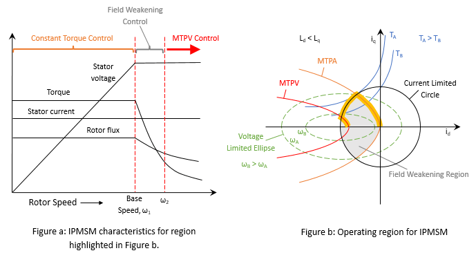
PMSM Drive Characteristics and Constraint Curves
Uses Motor Control Blockset™ to show how to use the PMSM characteristic plotting and PMSM milestone speed identification functions to obtain a control trajectory.
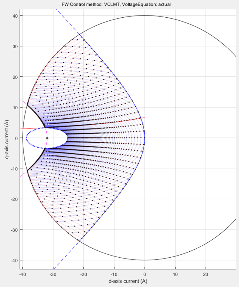
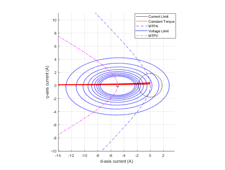
PMSM Constraint Curves and Their Application
Uses Motor Control Blockset™ to explain the fundamentals of constraint curves, utilization of these curves to determine operating currents, and usage of the grid of these currents in simulation or deployment environments.
Ports
Input
Output
Parameters
Extended Capabilities
Version History
Introduced in R2020a