Brayton Cycle (Gas Turbine)
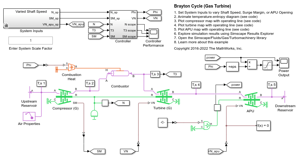
This example models a gas turbine auxiliary power unit (APU) based on the Brayton Cycle. The power input to the system is represented by heat injection into the combustor; actual combustion chemistry is not modeled. A single shaft connects the compressor and the turbine so that the power from the turbine drives the compressor. The APU is a free turbine that further expands the exhaust stream to produce output power.
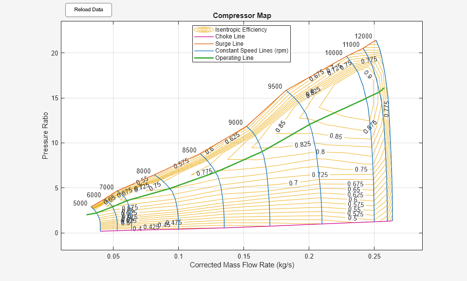
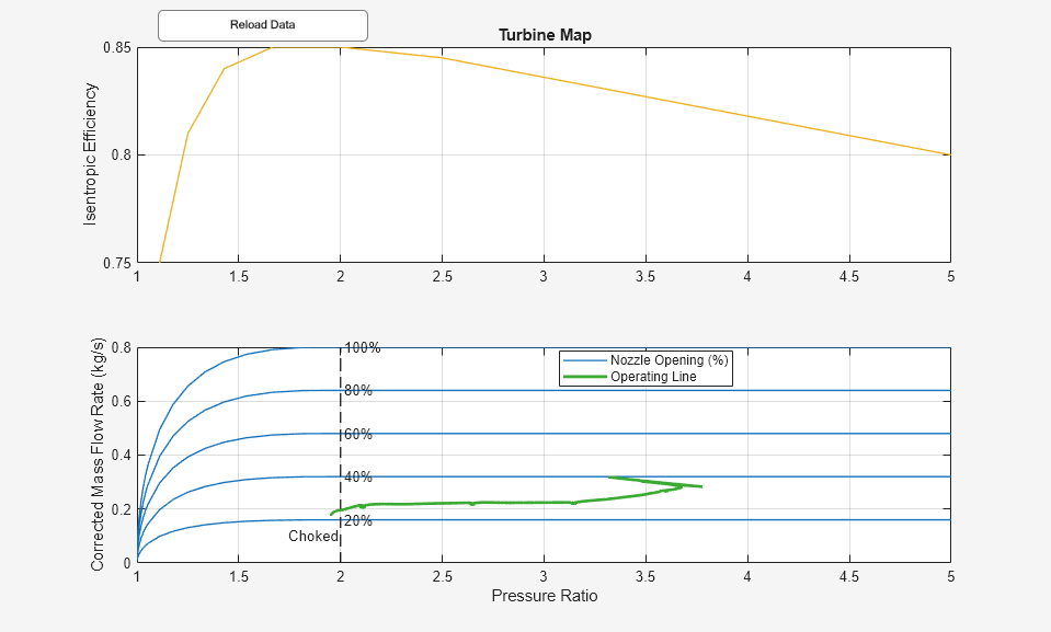
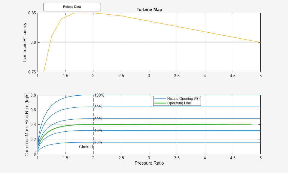
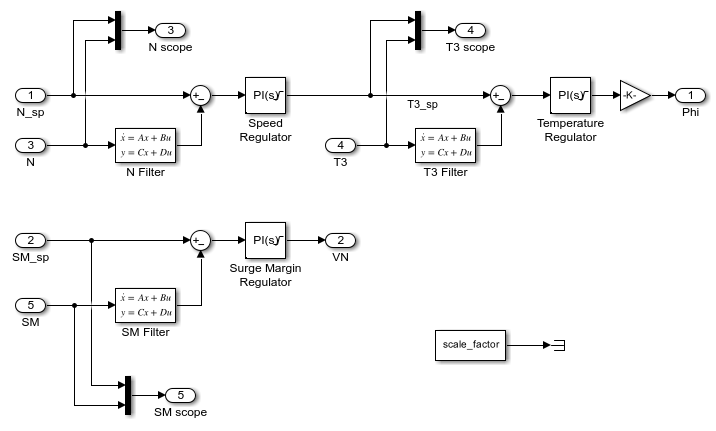
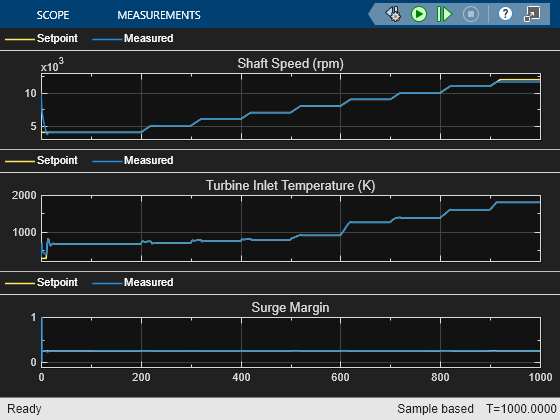
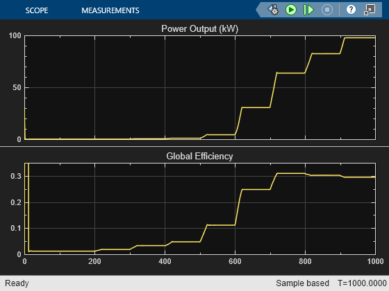
Three PID controllers regulate the shaft speed, the turbine inlet temperature, and the compressor surge margin. System inputs are defined for three scenarios: varying shaft speed, varying surge margin, and varying APU vane opening. Running the first scenario produces the typical operating line on the compressor map. Running the second and third scenarios show where the maximum power output and maximum global efficiency occurs.
The entire system can be scaled up or down by changing the scaling factor which is applied to all area and flow rate related parameters.
Model
Controller Subsystem
Simulation Results from Scopes
Animation of Simscape Logging Results
This figure shows an animation of the Brayton Cycle on a temperature-entropy diagram over time. The five cycle points on the figure correspond to the sensor measurements labeled "T,s 1" to "T,s 5", respectively.
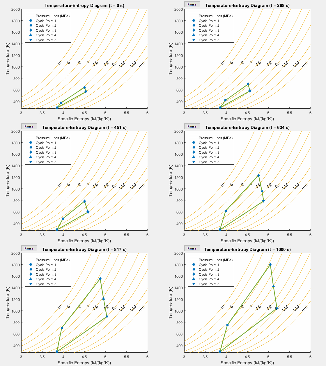
Simulation Results from Simscape Logging
