Fluid Transport
In this section, you can find examples of fluid transport in multiple Simscape Fluids domains.
Featured Examples
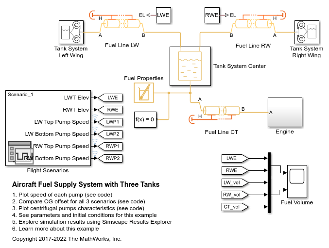
Aircraft Fuel Supply System with Three Tanks
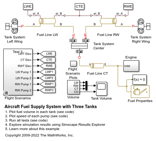
Model an aircraft fuel supply system consisting of three tanks and an engine.
Aircraft Fuel Supply System with Three Tanks
Warning: This example uses the hydraulic domain, which will be removed in a future release. Find an equivalent example model that uses the isothermal liquid domain here: Aircraft Fuel Supply System with Three Tanks. To convert models to the isothermal liquid domain, use the hydraulicToIsothermalLiquid tool.
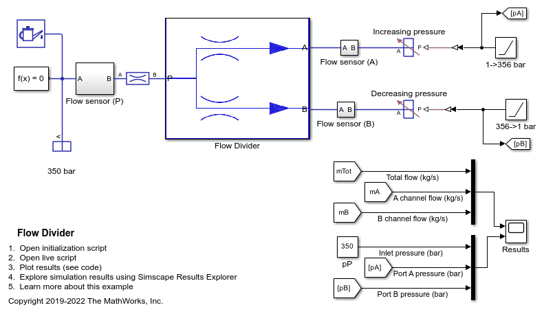
Flow Divider
A simple way of modeling of the flow divider and using it with the load harness. The flow divider helps in dividing the input flow in desired percentage when the loads connected to the two lines are unequal. Flow divider allows flow only in forward direction. Therefore when it is used with the loads where unloading is done through reverse flows, then it should be used in conjunction with the direction control valves.
Hydraulic Oil System with Thermal Control
A hydraulic oil system with a thermal control using Simscape™ Fluids™ Thermal Liquid blocks. The hydraulic oil system consists of an oil storage tank represented by the Tank (TL) block with two inlets, a pump represented by a Mass Flow Rate Source (TL) block, and pipelines represented by Pipe (TL) block.
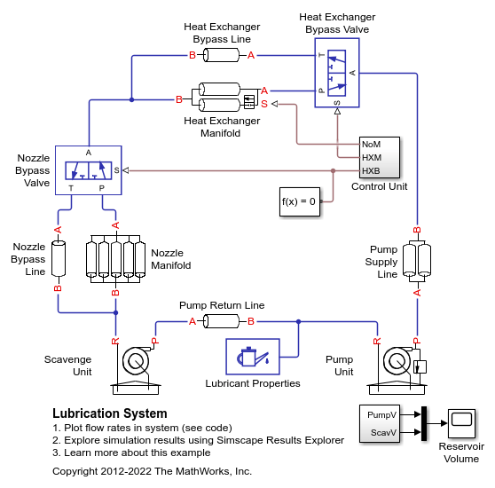
Lubrication System
A simplified version of a lubrication system fed with the centrifugal pump. The system consists of five major units: Pump Unit, Scavenge Unit, Heat Exchanger Manifold, Nozzle Manifold, and Control Unit. Both the pump and the scavenge unit are built around the centrifugal pump. The Scavenge Unit collects fluid discharged by nozzles and pumps it back into the reservoir of the Pump Unit. The Control Unit generates commands to bypass either the heat exchanger, represented as a local resistance, or the nozzles block. In a real system, these commands are generated by temperature sensors installed in lubrication cavities.
Lubrication System
Warning: This example uses the hydraulic domain, which will be removed in a future release. Find an equivalent example model that uses the isothermal liquid domain here: Lubrication System. To convert models to the isothermal liquid domain, use the hydraulicToIsothermalLiquid tool.
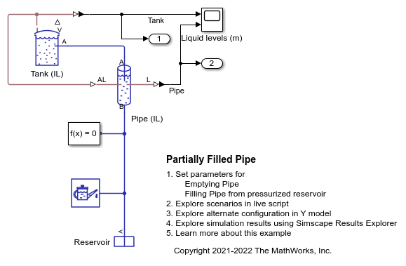
Partially Filled Pipe
The Partially Filled Pipe (IL) block used to model the emptying and filling of a tank in multiple configurations. You can use the live script provided with this example to understand the effect of different configurations.
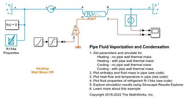
Pipe Fluid Vaporization and Condensation
The 3-Zone Pipe (2P) block used to model vaporization or condensation of fluid flow in a pipe. The block divides the internal fluid volume into up to three zones: liquid zone, mixture zone, and vapor zone, depending on the state of the fluid along the pipe. As fluid flows through the pipe, heat is transferred between the environment external to the pipe and the fluid inside the pipe, causing it to change from liquid to mixture to vapor for the heating case or from vapor to mixture to liquid for the cooling case. The effect of thermal storage in the pipe wall can be optionally turned on by specifying a nonzero pipe wall thickness.
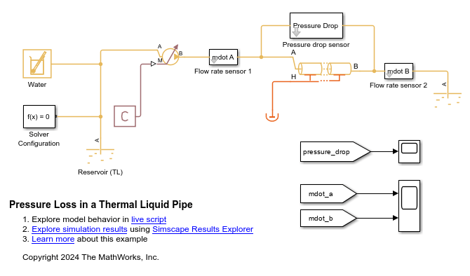
Pressure Loss and Mass Flow Rate in a Thermal Liquid Pipe
How changes in pipe and fluid attributes, such as friction and elevation change, impact the pressure loss through a pipe and how enabling dynamic compressibility impacts the mass flow rate. These effects are especially important in long, narrow pipes because they ensure the flow pressure is strong enough to overcome the pressure loss. This example uses the Simscape™ Fluids™ Pipe (TL) block.
Water Hammer Effect
This demo shows how the Isothermal Liquid library can be used to model water hammer in a long pipe. After opening a valve to slowly establish steady flow in the pipe, the valve is quickly shut. If the Valve is shut quickly enough, it triggers a water hammer effect. A water hammer arrestor suppresses the pressure spikes.
MATLAB Command
You clicked a link that corresponds to this MATLAB command:
Run the command by entering it in the MATLAB Command Window. Web browsers do not support MATLAB commands.
Select a Web Site
Choose a web site to get translated content where available and see local events and offers. Based on your location, we recommend that you select: .
You can also select a web site from the following list
How to Get Best Site Performance
Select the China site (in Chinese or English) for best site performance. Other MathWorks country sites are not optimized for visits from your location.
Americas
- América Latina (Español)
- Canada (English)
- United States (English)
Europe
- Belgium (English)
- Denmark (English)
- Deutschland (Deutsch)
- España (Español)
- Finland (English)
- France (Français)
- Ireland (English)
- Italia (Italiano)
- Luxembourg (English)
- Netherlands (English)
- Norway (English)
- Österreich (Deutsch)
- Portugal (English)
- Sweden (English)
- Switzerland
- United Kingdom (English)
