FIR Interpolator
Libraries:
DSP HDL Toolbox /
Filtering
Description
The FIR Interpolator block implements a single-rate polyphase FIR interpolation filter that is optimized for HDL code generation. The block provides a hardware-friendly interface with input and output control signals. To provide a cycle-accurate simulation of the generated HDL code, the block models architectural latency including pipeline registers and resource sharing.
The block accepts scalar or vector input and outputs a scalar or vector depending on the interpolation factor and the number of cycles between input samples. The block implements a polyphase decomposition with InterpolationFactor subfilters. The filter can implement a serial architecture if there is regular spacing between input samples.
The block provides two filter structures. The direct form systolic architecture provides an implementation that makes efficient use of Intel® and Xilinx® DSP blocks. This architecture can be fully-parallel or serial. To use a serial architecture, the input samples must be spaced out with a regular number of invalid cycles between the valid samples. The direct form transposed architecture is a fully parallel implementation that is suitable for FPGA and ASIC applications. For a filter implementation that matches multipliers, pipeline registers, and pre-adders to the DSP configuration of your FPGA vendor, specify your target device when you generate HDL code.
For scalar input, all filter structures optimize hardware resources by sharing multipliers for symmetric or antisymmetric filters and by removing the multipliers for zero-valued coefficients such as in half-band filters and Hilbert transforms. When your input is a vector, the filter structure removes the multipliers for zero-valued coefficients but does not optimize for symmetric coefficients.
Note
You can also generate HDL code for this hardware-optimized algorithm, without creating a Simulink® model, by using the DSP HDL IP Designer app. The app provides the same interface and configuration options as the Simulink block.
Examples
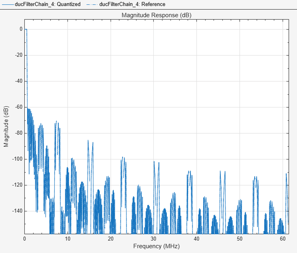
Implement Digital Upconverter for FPGA
Design a digital upconverter (DUC) for LTE on FPGAs.

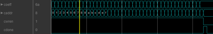
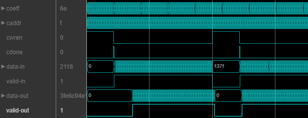
Programmable FIR Filter for FPGA
Implement a programmable FIR filter for hardware and load the filter coefficients by using a memory-style interface.
Ports
Input
Input data, specified as a real or complex scalar or vector. The vector size must be less than or equal to 64.
The block has an output ready signal that indicates when the block is ready to process new input data. Your design can react to the ready signal to provide the next input sample, or you can space your input data with enough cycles in between that the block can process each sample. For more information, see Backpressure Signal.
When the input data type is an integer type or a fixed-point type, the block uses fixed-point arithmetic for internal calculations and provides parameters on the Data Types tab to customize the data types. When the input data type is a floating-point type, the block uses that input floating-point type for internal calculations and the output data type.
The software supports double and
single data types for simulation, but not for HDL code generation.
Data Types: fixed point | single | double | int8 | int16 | int32 | uint8 | uint16 | uint32
Complex Number Support: Yes
Control signal that indicates if the input data is valid. When
valid is 1 (true), the
block captures the values from the input data port. When
valid is 0 (false), the
block ignores the values from the input data port.
Data Types: Boolean
Since R2025a
Filter coefficients, specified as a row vector of real or complex values. You can change the input coefficients at any time. The size of the coefficient vector must match the size of the sample coefficients specified in the Coefficients prototype parameter. The prototype specifies a sample coefficient vector that is representative of the zero-valued locations of the expected input coefficients. The block uses the prototype to optimize the filter by removing multipliers for zero-valued coefficients.
If the input data is a fixed-point type, the coeff values must also be of a fixed point type. If the input data is a floating-point data type, the coeff values must be of the same data type.
The software supports double and
single data types for simulation, but not for HDL code generation.
Dependencies
To enable this port, set Coefficients source to
Input port (Parallel interface).
Data Types: single | double | int8 | int16 | int32 | uint8 | uint16 | uint32 | fixed point
Since R2026a
Filter coefficients, specified as a real or complex scalar value to write to internal memory. To load a single coefficient value to internal memory, specify a coeff value with a corresponding address on the caddr port and an enable signal on the cwren port. You can change the input coefficients at any time.
While you write new coefficients into memory, the block ignores any input data,
but still returns dataOut with validOut
until it clears the filter pipeline. The block resumes accepting input the cycle after
cdone is set to 1 (true).
The coefficient memory has the same number of addresses as the size of the Coefficients prototype parameter. The prototype specifies a sample coefficient vector that is representative of the zero-valued locations of the expected input coefficients. When you use scalar input data, the block uses the prototype to optimize the filter by sharing multipliers for symmetric or antisymmetric coefficients, and by removing multipliers for zero-valued coefficients. You must write the entire set of coefficients to memory, including symmetric or zero-value coefficients. For example, if you set the Coefficients prototype parameter to a symmetric 14-tap filter, you must write 14 values to the memory interface.
When you use frame-based input data, the block does not optimize the filter for coefficient symmetry. The block still uses the Coefficients prototype parameter to remove multipliers for zero-valued coefficients. The coefficient memory has the same number of locations as the size of the prototype.
If the input data is a fixed-point type, the coeff values must also be of a fixed point type. If the input data is a floating-point data type, the coeff values must be of the same data type.
The software supports double and
single data types for simulation, but not for HDL code generation.
Dependencies
To enable this port, set Coefficients source to
Input
                  port (Memory interface)
.
Data Types: single | double | int8 | int16 | int32 | uint8 | uint16 | uint32 | fixed point
Since R2026a
Specify the filter coefficient address as a scalar integer value represented as an unsigned fixed-point type with zero fractional bits. The block derives the size of this integer value, and the size of the internal memory, from the number of unique coefficients in the Coefficients prototype parameter value.
Dependencies
To enable this port, set Coefficients source to
Input
          port (Memory interface)
.
Data Types: fixdt(0,N,0)
Since R2026a
Set this input to 1 (true) to write the
value on the coeff port into the caddr
location in internal memory.
Dependencies
To enable this port, set Coefficients source to
Input port (Memory interface).
Data Types: Boolean
Since R2026a
Set this input to 1 (true) to indicate that
writing coefficients to memory is complete. You can set this input to
1 (true) along with the last coefficient
write, or on a later cycle with no active write.
Dependencies
To enable this port, set Coefficients source to
Input port (Memory interface).
Data Types: Boolean
Control signal that clears internal states. When reset is
1 (true), the block stops the current
calculation and clears internal states. When the reset is
0 (false) and the input
valid is 1 (true), the
block captures data for processing.
For more reset considerations, see the Reset Signal section on the Hardware Control Signals page.
Dependencies
To enable this port, on the Control Ports tab, select Enable reset input port.
Data Types: Boolean
Output
Parameters
Algorithms
The block implements a polyphase filter bank where the filter coefficients are decomposed into InterpolationFactor subfilters. If the filter length is not divisible by the Interpolation factor parameter value, then the block zero-pads the coefficients. When your input is regularly spaced, with two or more cycles between valid samples, as indicated by the Minimum number of cycles between valid input samples parameter, the filter can share multiplier resources in time.
This flow chart shows which filter architectures result from your parameter settings. It also shows the number of multipliers used by the filter implementation. The filter architecture depends on the input frame size, V, the interpolation factor, R, the number of cycles between valid input samples, N, and the number of filter coefficients, L. The architectures are in order from lowest resource use on the left, to higher resources on the right. The higher resource architectures are trading off resource use for higher throughput. Each architecture is described below the flow chart.
If the filter is symmetric and you select
Optimize symmetric coefficients, the architecture shares multipliers
for matching coefficients. In that case the number of filter coefficients,
L, in the flow chart represents
NumCoeffs/2. This option is supported only with scalar
input. (since R2024b)
The number of multipliers shown in the flow chart is for filters with real input and real coefficients. For complex input, the filter uses three times as many multipliers.

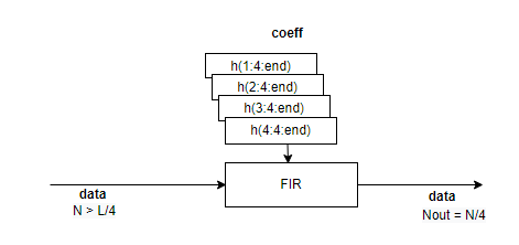
Architectures 1 and 2 — Serial polyphase interleaved filter bank.
When NumCycles is greater than FilterLength/InterpolationFactor, the block interleaves each phase of coefficients over a single FIR filter to share resources between phases. The single FIR filter has a serial architecture and uses the NumCycles value to share multipliers over time. A partly serial filter uses FilterLength/NumCycles multipliers. When NumCycles is greater than the filter length, the filter becomes fully serial and uses one multiplier. The diagram shows a filter with an interpolation factor of 4 and at least FilterLength/4 cycles between input samples.
When you select Optimize symmetric coefficients, the decomposed sets of coefficients may not have the same symmetry and zero locations, which means the architecture cannot share the subfilter. In this case, the filter uses architecture 3/4, where each set of coefficients has its own subfilter.
Architectures 3 and 4 — Partly serial polyphase filter bank.
Each subfilter of the polyphase decomposition uses the NumCycles value to implement a serial filter. When NumCycles is FilterLength/InterpolationFactor, each phase uses a single multiplier, for a total of InterpolationFactor multipliers. The output is a vector if NumCycles < InterpolationFactor and a scalar if NumCycles ≥ InterpolationFactor.
The diagram shows a polyphase filter bank with scalar input and InterpolationFactor is set to 4. NumCycles is 2. Each subfilter is partly serial and has FilterLength/(4*2) multipliers, for a total of FilterLength/2 multipliers. The output is a vector because the interpolation factor is larger than the number of cycles between input samples.
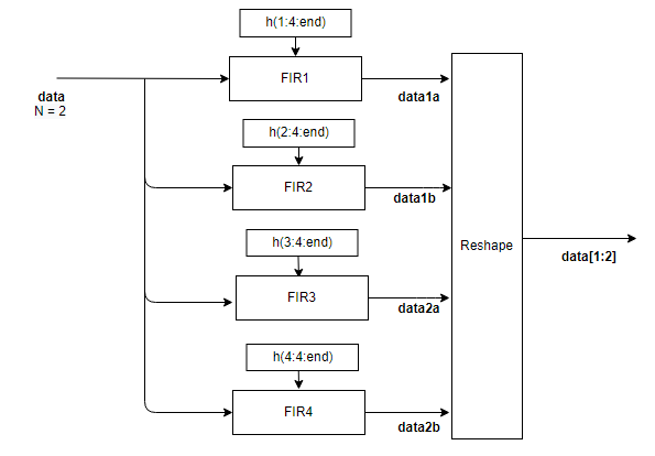
Architectures 5 and 6 — Fully parallel polyphase filter bank.
The diagram shows the polyphase filter bank with scalar input and InterpolationFactor is set to 4. The NumCycles value is 1, so the output must be a vector and each subfilter contributes one sample to the output vector. Each subfilter is a fully parallel FIR filter, with L/4 multipliers, for a total of L multipliers.

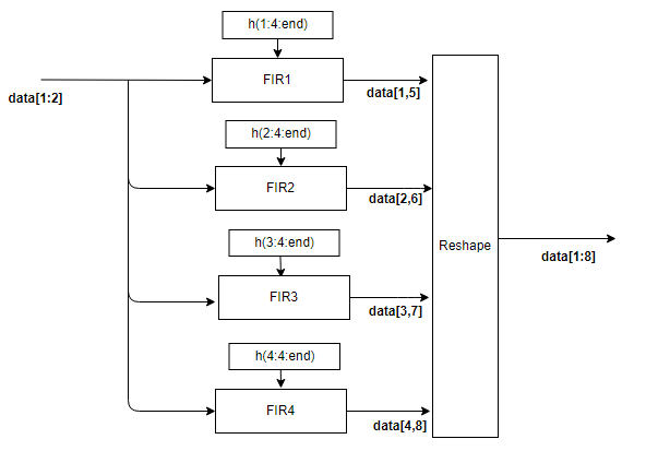
When the input is a vector, each subfilter is a frame-based filter that contains one parallel filter for each input sample. This diagram shows the polyphase filter bank for an input vector of two values and InterpolationFactor is set to 4. Each of the four subfilters generates two samples of the output vector and contains L/4*2 multipliers, for a total of L*2 multipliers.
Each subfilter is implemented with a Discrete FIR Filter block. For architecture details, see FIR Filter Architectures for FPGAs and ASICs.