NCO
Generate real or complex sinusoidal signals
Libraries:
DSP System Toolbox /
Signal Operations
DSP System Toolbox /
Sources
Description
The NCO block generates a multichannel real or complex sinusoidal
signal, with independent frequency and phase in each output channel. The amplitude of
the created signal is always 1. The NCO block supports
real inputs only. All outputs are real except for the output signal in
Complex exponential mode. For more information on how the
block computes the output, see Algorithms.
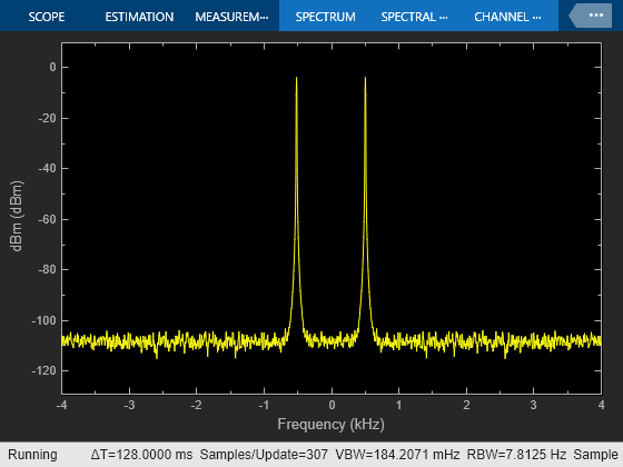
To produce a multichannel output, specify a vector quantity for the Phase increment and Phase offset parameters. Both parameters must have the same length, which defines the number of output channels. Each element of each vector is applied to a different output channel.
Examples
Ports
Input
Output
Parameters
Block Characteristics
Data Types |
|
Direct Feedthrough |
|
Multidimensional Signals |
|
Variable-Size Signals |
|
Zero-Crossing Detection |
|
More About
Algorithms
The block implements the algorithm as shown in the following diagram:

The implementation of a numerically controlled oscillator (NCO) has two distinct parts. First, a phase accumulator accumulates the phase increment and adds in the phase offset. In this stage, an optional internal dither signal can also be added. The NCO output is then calculated by quantizing the results of the phase accumulator section and using them to select values from a lookup table. Since the lookup table contains a finite set of entries, in its normal mode of operation, the NCO block allows the adder’s numeric values to overflow and wrap around. The Fixed-Point infrastructure then causes overflow warnings to appear on the command line. This overflow is of no consequence.
Given a desired output frequency F0, calculate the value of the Phase increment block parameter with
where N is the accumulator word length and
The frequency resolution of an NCO is defined by
Given a desired phase offset (in radians), calculate the Phase offset block parameter with
The spurious free dynamic range (SFDR) is estimated as follows for a lookup table with entries, where P is the number of quantized accumulator bits:
The NCO block uses a quarter-wave lookup table technique that stores table values from 0 to π/2. The block calculates other values on demand using the accumulator data type, then casts them into the output data type. This can lead to quantization effects at the range limits of a given data type. For example, consider a case where you would expect the value of the sine wave to be –1 at π. Because the lookup table value at that point must be calculated, the block might not yield exactly –1, depending on the precision of the accumulator and output data types.
Extended Capabilities
Version History
Introduced before R2006a
See Also
Blocks
- PN Sequence Generator (Communications Toolbox) | Sine Wave | Digital Down-Converter | Digital Up-Converter


