Simulate Simple Driving Scenario and Sensor in Unreal Engine Environment
Automated Driving Toolbox™ provides blocks for visualizing sensors in a simulation environment that uses the Unreal Engine® from Epic Games®. This model simulates a simple driving scenario in a prebuilt scene and captures data from the scene using a fisheye camera sensor. Use this model to learn the basics of configuring and simulating scenes, vehicles, and sensors. For more background on the Unreal Engine simulation environment, see Unreal Engine Simulation for Automated Driving.
Model Overview
The model consists of these main components:
Scene — A Simulation 3D Scene Configuration block configures the scene in which you simulate.
Vehicles — Two Simulation 3D Vehicle with Ground Following blocks configure the vehicles within the scene and specify their trajectories.
Non-vehicle Actors — Simulation 3D Pedestrian and Simulation 3D Bicyclist blocks configure a pedestrian and a bicyclist, and specify their trajectories respectively.
Sensor — A Simulation 3D Fisheye Camera configures the mounting position and parameters of the fisheye camera used to capture simulation data. A Video Viewer block visualizes the simulation output of this sensor.

model = 'SimpleScenarioAndSensorModel3DSimulation';
open_system(model)
Inspect Scene
In the Simulation 3D Scene Configuration block, the Scene name parameter determines the scene where the simulation takes place. This model uses the Large Parking Lot scene, but you can choose among several prebuilt scenes. To explore a scene, you can open the 2D image corresponding to the 3D scene.
data = load('sim3d_SpatialReferences.mat');
spatialRef = data.spatialReference.LargeParkingLot;
figure; imshow('sim3d_LargeParkingLot.jpg',spatialRef)
set(gca,'YDir','normal')
sceneName = 'LargeParkingLot';
[sceneImage, sceneRef] = helperGetSceneImage(sceneName);

hScene = figure;
helperShowSceneImage(sceneImage, sceneRef)
title(sceneName)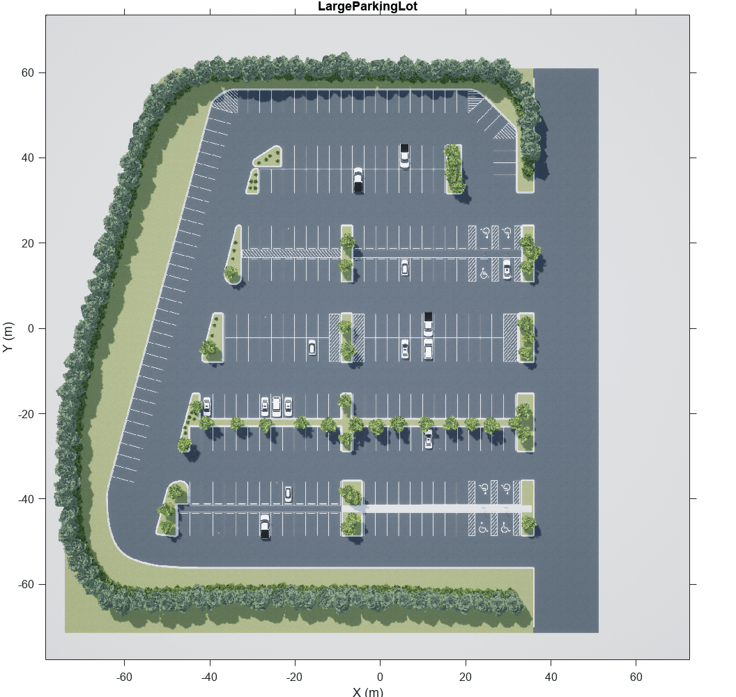
To learn how to explore other scenes, see the corresponding scene reference pages.
The Scene view parameter of this block determines the view from which the Unreal Engine window displays the scene. In this block, Scene view is set to EgoVehicle, which is the name of the ego vehicle (the vehicle with the sensor) in this scenario. During simulation, the Unreal Engine window displays the scene from behind the ego vehicle. You can also change the scene view to the other vehicle. To display the scene from the root of the scene (the scene origin), select root.
The Weather tab of the block controls the sun position and scene weather. This scene is configured to take place at noon and is cloudy with light rain.
Inspect Vehicles
The Simulation 3D Vehicle with Ground Following blocks model the vehicles in the scenario.
The Ego Vehicle block vehicle contains the fisheye camera sensor. This vehicle is modeled as a red hatchback.
The Target Vehicle block is the vehicle from which the sensor captures data. This vehicle is modeled as a green SUV.
During simulation, both vehicles travel straight in the parking lot for 50 meters. The target vehicle is 10 meters directly in front of the ego vehicle.
xlabel('X (m)')
ylabel('Y (m)')

xyOffset = 3;

x = 45 - xyOffset;
y = 0 - xyOffset;
w = 3;
h = 6;
distAhead = 10;
distTraveled = 50;

egoStart = rectangle('Position',[x y w h],'FaceColor','r');
targetStart = rectangle('Position',[x y+distAhead w h],'FaceColor','g');

egoEnd = rectangle('Position',[x y+distTraveled w h],'FaceColor','r');
targetEnd = rectangle('Position',[x y+distTraveled+distAhead w h],'FaceColor','g');


xTextOffset = 30;
startText = text(x-xTextOffset, y+distAhead, 'Starting Positions', ...
    'EdgeColor','black','BackgroundColor','White');

endText = text(x-xTextOffset, y+distTraveled+distAhead, 'Ending Positions', ...
    'EdgeColor','black','BackgroundColor','White');
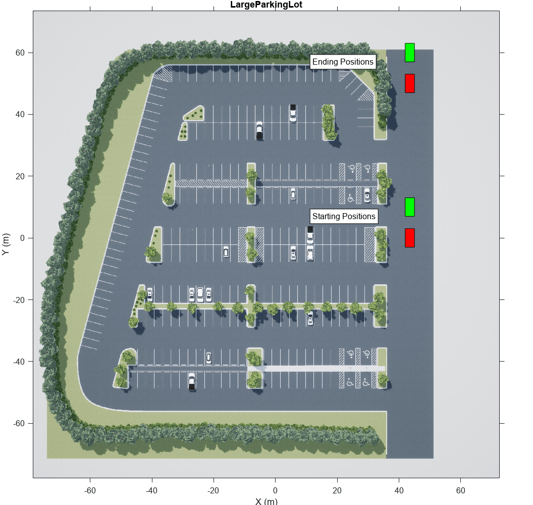
The X, Y, and Yaw input ports control the trajectories of these vehicles. X and Y are in the world coordinates of the scene, which are in meters. Yaw is the orientation angle of the vehicle and is in degrees.
The ego vehicle travels from a position of (45,0) to (45,50), oriented 90 degrees counterclockwise from the origin. To model this position, the input port values are as follows:
X is a constant value of
45.Y is a multiple of the simulation time. A Digital Clock block outputs the simulation time every 0.1 second for 5 seconds, which is the stop time of the simulation. These simulation times are then multiplied by 10 to produce Y values of
[0 1 2 3 ... 50], or 1 meter for up to a total of 50 meters.Yaw is a constant value of
90.
The target vehicle has the same X and Yaw values as the ego vehicle. The Y value of the target vehicle is always 10 meters more than the Y value of the ego vehicle.
In both vehicles, the Initial position [X, Y, Z] (m) and Initial rotation [Roll, Pitch, Yaw] (deg) parameters reflect the initial [X, Y, Z] and [Yaw, Pitch, Roll] values of the vehicles at the beginning of simulation.
To create more realistic trajectories, you can obtain waypoints from a scene interactively and specify these waypoints as inputs to the Simulation 3D Vehicle with Ground Following blocks. See Select Waypoints for Unreal Engine Simulation.
Both vehicles also have the optional Light controls input port enabled. This port enables you to specify a logical vector specifying whether the headlights, brake lights, reverse lights, or turn signal lights are on. Both vehicles have a 1 in the second position of the vector, which turns on their low beam headlights. For more details on enabling and controlling vehicle lights, see the Simulation 3D Vehicle with Ground Following block reference page.
Inspect Non-Vehicle Actors
The Simulation 3D Pedestrian and the Simulation 3D Bicyclist blocks model the pedestrian and the bicyclist respectively. The pedestrian is stationary at the position of (40,27.7) and is oriented towards the moving vehicles. Open the Simulation 3D Pedestrian block parameters to change the type of pedestrian, scale their size, and change the name. You can specify the type of the pedestrian to be either male, female or a child.
The bicyclist starts from the position of (50,0) and follows the two moving vehicles in a straight line on their left. Open the Simulation 3D Bicyclist block parameters to scale their size and change the name.
Inspect Sensor
The Simulation 3D Fisheye Camera block models the sensor used in the scenario. Open this block and inspect its parameters.
The Mounting tab contains parameters that determine the mounting location of the sensor. The fisheye camera sensor is mounted to the center of the roof of the ego vehicle.
The Parameters tab contains the intrinsic camera parameters of a fisheye camera. These parameters are set to their default values, with the exception of the Mapping coefficients parameter. In this parameter, the second coefficient is decreased from
0to-0.0005to model lens distortion.The Ground Truth tab contains a parameter for outputting the location and orientation of the sensor in meters and radians. In this model, the block outputs these values so you can see how they change during simulation.
The block outputs images captured from the simulation. During simulation, the Video Viewer block displays these images.
Simulate Model
Simulate the model. When the simulation begins, it can take a few seconds for the visualization engine to initialize, especially when you are running it for the first time. The AutoVrtlEnv window shows a view of the scene in the 3D environment.
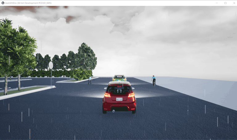
The Video Viewer block shows the output of the fisheye camera.
sim(model);

To change the view of the scene during simulation, use the numbers 1–9 on the numeric keypad.
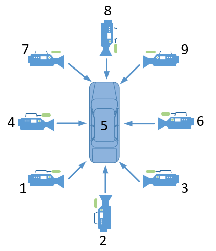
For a bird's-eye view of the scene, press 0.
After simulating the model, try modifying the intrinsic camera parameters and observe the effects on simulation. You can also change the type of sensor block. For example, try substituting the 3D Simulation Fisheye Camera with a 3D Simulation Camera block. For more details on the available sensor blocks, see Choose a Sensor for Unreal Engine Simulation.
See Also
Simulation 3D Scene Configuration | Simulation 3D Vehicle with Ground Following | Simulation 3D Camera | Simulation 3D Fisheye Camera | Simulation 3D Probabilistic Radar | Simulation 3D Lidar | Simulation 3D Vision Detection Generator
Topics
- Unreal Engine Simulation for Automated Driving
- Unreal Engine Simulation Environment Requirements and Limitations
- How Unreal Engine Simulation for Automated Driving Works
- Coordinate Systems in Automated Driving Toolbox
- Select Waypoints for Unreal Engine Simulation
- Design Lane Marker Detector Using Unreal Engine Simulation Environment