Main Content

ultrasonicDetectionGenerator

Generate ultrasonic range detections in driving scenario or RoadRunner Scenario

Since R2022a

Description

The ultrasonicDetectionGenerator System object™ generates detections from an ultrasonic sensor mounted on an ego vehicle. The detections are range measurements that indicate the distance between the sensor and the closest point of the detected object. You can use an ultrasonicDetectionGenerator object in a scenario containing actors and trajectories, which you can create by using a drivingScenario object.

You can also use the ultrasonicDetectionGenerator object with vehicle actors in RoadRunner Scenario simulation. First you must create a SensorSimulation object to interface sensors with RoadRunner Scenario and then register the lidar as a sensor model using the addSensors object function before simulation.

To generate ultrasonic detections:

  1. Create the ultrasonicDetectionGenerator object and set its properties.

  2. Call the object with arguments, as if it were a function.

To learn more about how System objects work, see What Are System Objects?

Creation

Description

ultrasonic = ultrasonicDetectionGenerator creates an ultrasonicDetectionGenerator object with default property values to generate range detections for a simulated ultrasonic sensor.

ultrasonic = ultrasonicDetectionGenerator(Name=Value) sets properties using one or more name-value arguments. For example, ultrasonicDetectionGenerator(MountingLocation=[1 0 0.5],MountingAngles=[0 0 pi/20]) specifies the mounting location and angle of the ultrasonic sensor on the ego vehicle.

Properties

expand all

Unless otherwise indicated, properties are nontunable, which means you cannot change their values after calling the object. Objects lock when you call them, and the release function unlocks them.

If a property is tunable, you can change its value at any time.

For more information on changing property values, see System Design in MATLAB Using System Objects.

Unique sensor identifier, specified as a positive integer. This property distinguishes detections that come from different sensors in a multisensor system.

Example: 5

Data Types: double

Sensor update rate, specified as a positive real scalar, in Hz. The value of this property must be an integer multiple of the simulation update rate defined by the associated drivingScenario object. Simulation updates between sensor updates contain no detections

Example: 5

Data Types: double

Sensor mounting location on the ego vehicle, specified as a 1-by-3 real-valued vector of the form [x y z]. This property defines the coordinates of the sensor in meters, along the x-, y-, and z-axes relative to the ego vehicle origin, where:

  • The x-axis points forward from the vehicle.

  • The y-axis points to the left of the vehicle.

  • The z-axis points up from the ground.

The default value defines an ultrasonic sensor that is mounted at the center of the front bumper of a sedan.

For more details on the ego vehicle coordinate system, see Coordinate Systems in Automated Driving Toolbox.

Data Types: double

Sensor mounting orientation on ego vehicle, specified as a 1-by-3 real-valued vector of form [zyaw ypitch xroll]. This property defines the intrinsic Euler angle rotation of the sensor, in degrees, around the z-, y-, and x-axes with respect to the ego vehicle body frame, where:

  • zyaw, or yaw angle, rotates the sensor around the z-axis of the ego vehicle.

  • ypitch, or pitch angle, rotates the sensor around the y-axis of the ego vehicle. This rotation is relative to the sensor position that results from the zyaw rotation.

  • xroll, or roll angle, rotates the sensor around the x-axis of the ego vehicle. This rotation is relative to the sensor position that results from the zyaw and ypitch rotations.

These angles are clockwise-positive when looking in the forward direction of the z-axis, y-axis, and x-axis, respectively. If you visualize sensor data from a bird's-eye view perspective, then the yaw angle is counterclockwise-positive because you are viewing the data in the negative direction of the z-axis, which points up from the ground.

For more details on this coordinate system, see Coordinate Systems in Automated Driving Toolbox.

Data Types: double

Angular field of view of the ultrasonic sensor, specified as a 1-by-2 positive real-valued vector of the form [azfov elfov]. The field of view defines the total angular extent spanned by the sensor. You must specify the azimuth field of view azfov in the range (0, 360], and the elevation field of view elfov in the range (0, 180]. Units are in degrees.

Data Types: double

Detection range vector of the ultrasonic sensor, specified as a 1-by-3 nonnegative real-valued vector of the form [minDetOnlyRange minDistRange maxDistRange], where minDetOnlyRange < minDistRange < maxDistRange. Units are in meters. These values determine the detections and distance values returned by the ultrasonic sensor.

  • When the detected object is at a distance between minDistRange and maxDistRange, the sensor returns a positive distance value.

  • When the detected object is at a distance between minDetOnlyRange and minDistRange, the sensor detects the object, but cannot determine the distance and returns a value of 0.

  • When the object is at a distance below minDetOnlyRange or above maxDistRange, the sensor returns an empty cell array.

Data Types: double

Actor profiles, specified as a structure or as an array of structures. Each structure contains the physical and radar characteristics of an actor.

  • If ActorProfiles is a single structure, all actors passed into the ultrasonicDetectionGenerator object use this profile.

  • If ActorProfiles is an array, each actor passed into the object must have a unique actor profile.

To generate an array of structures for your driving scenario, use the actorProfiles function. The table shows the valid structure fields. If you do not specify a field, that field is set to its default value. If no actors are passed into the object, then the ActorID field is not included.

FieldDescription
ActorIDScenario-defined actor identifier, specified as a positive integer.
ClassIDClassification identifier, specified as a nonnegative integer. 0 is reserved for an object of an unknown or unassigned class.
LengthLength of actor, specified as a positive real scalar. The default is 4.7. Units are in meters.
WidthWidth of actor, specified as a positive real scalar. The default is 1.8. Units are in meters.
HeightHeight of actor, specified as a positive real scalar. The default is 1.4. Units are in meters.
OriginOffset

Offset of the rotational center of the actor from its geometric center, specified as an [x y z] real-valued vector. The rotational center, or origin, is located at the bottom center of the actor. For vehicles, the rotational center is the point on the ground beneath the center of the rear axle. The default is [-1.35 0 0]. Units are in meters.

RCSPatternRadar cross-section pattern of actor, specified as a numel(RCSElevationAngles)-by-numel(RCSAzimuthAngles) real-valued matrix. The default is [10 10; 10 10]. Units are in decibels per square meter.
RCSAzimuthAnglesAzimuth angles corresponding to rows of RCSPattern, specified as a vector of real values in the range [–180, 180]. The default is [-180 180]. Units are in degrees.
RCSElevationAnglesElevation angles corresponding to rows of RCSPattern, specified as a vector of real values in the range [–90, 90]. The default is [-90 90]. Units are in degrees.

For full definitions of the structure fields, see the actor and vehicle functions.

Data Types: struct

Usage

Description

dets = ultrasonic(targets,simTime) creates ultrasonic detections, dets, from sensor measurements taken of target poses, targets, relative to the ego vehicle at the current simulation time simTime. The object can generate sensor detections for multiple actors simultaneously.

example

[dets,isValidTime] = ultrasonic(targets,simTime) also returns a logical value, isValidTime, indicating whether simTime is a valid time for generating detections. If simTime is an integer multiple of the reciprocal of the UpdateRate property value, then isValidTime is 1 (true).

Input Arguments

expand all

Target actor poses, specified as a structure or structure array. Each structure describes the pose of a target actor relative to the ego vehicle. To generate these structures, use the targetPoses function. You can also create these structures manually. Do not include the ego vehicle pose in this argument.

This table shows the required fields for the structures.

FieldDescription
ActorID

Scenario-defined actor identifier, specified as a positive integer.

ClassIDClassification identifier, specified as a nonnegative integer. 0 represents an object of an unknown or unassigned class.
Position

Position of actor, specified as a real-valued vector of the form [x y z]. Units are in meters.

Velocity

Velocity (v) of actor in the x-, y-, and z-directions, specified as a real-valued vector of the form [vx vy vz]. Units are in meters per second.

Roll

Roll angle of actor, specified as a real scalar. Units are in degrees.

Pitch

Pitch angle of actor, specified as a real scalar. Units are in degrees.

Yaw

Yaw angle of actor, specified as a real scalar. Units are in degrees.

AngularVelocity

Angular velocity (ω) of actor in the x-, y-, and z-directions, specified as a real-valued vector of the form [ωx ωy ωz]. Units are in degrees per second.

Current simulation time, specified as a nonnegative real scalar in seconds.

Example: 10.5

Data Types: double

Output Arguments

expand all

Generated detections, returned as a cell array of objectDetection objects. Each object contains these properties:

PropertyDescription
TimeMeasurement time
MeasurementDistance measurement to the closest object
MeasurementNoiseMeasurement noise covariance matrix
SensorIndexUnique ID of the sensor
ObjectClassIDObject classification
ObjectAttributesAdditional information passed to tracker
MeasurementParametersParameters used by initialization functions of nonlinear Kalman tracking filters

This table describes the additional information in the ObjectAttributes property.

ObjectAttributes

AttributeDefinition
TargetIndexIdentifier of the actor, ActorID, that generated the detection. For false alarms, this value is negative.
PointOnTargetCoordinate of the point on the detected object that the sensor used to compute the distance measurement. It is in the vehicle coordinate system.

For MeasurementParameters, the measurements are relative to the parent frame. The parent frame is the ego vehicle body.

MeasurementParameters

ParameterDefinition
Frame Enumerated type indicating the frame used to report measurements. The Frame is always set to 'spherical' and the detections are reported in spherical coordinates for ultrasonicDetectionGenerator.
OriginPosition3-D vector offset of the sensor origin from the parent frame origin.
OriginVelocityVelocity of the sensor coordinate system with respect to the parent frame.
IsParentToChildLogical scalar indicating if Orientation performs a frame rotation from the parent coordinate frame to the child coordinate frame. When IsParentToChild is false, then Orientation performs a frame rotation from the child coordinate frame to the parent coordinate frame.
HasAzimuthIndicates whether measurements contain azimuth components.
HasRangeIndicates whether measurements contain range components. Always true for ultrasonicDetectionGenerator.
HasElevationIndicates whether measurements contain elevation components. Always false for Ultrasonic Detection Generator.
HasVelocityIndicates whether measurements contain velocity or range rate components. Always false for ultrasonicDetectionGenerator.
FieldOfView2-D vector containing the azimuth and elevation field of view values of the sensor.

Valid time for generating reports, returned as a logical 0 (false) or 1 (true).

If the reports dets generated by the sensor are invalid because the sensor generated them at a time inconsistent with the sensor update rate, then isValidTime is 0.

The sensor generates reports only when the current simulation time, simTime, is an integer multiple of the time interval at which the sensor generates reports. This time interval is equal to the reciprocal of the UpdateRate property value.

Data Types: logical

Object Functions

To use an object function, specify the System object as the first input argument. For example, to release system resources of a System object named obj, use this syntax:

release(obj)

expand all

stepRun System object algorithm
releaseRelease resources and allow changes to System object property values and input characteristics
resetReset internal states of System object
isLockedDetermine if System object is in use
cloneCreate duplicate System object

Examples

collapse all

Use a simulated ultrasonic sensor to generate detections for multiple vehicles in a driving scenario.

Create Driving Scenario

Create a driving scenario containing a three-lane road using lane specifications.

scenario = drivingScenario;
roadCenters = [-120 30 0;-60 0 0;0 0 0; 60 0 0; 120 30 0];
lspc = lanespec(3);
road(scenario,roadCenters,Lanes=lspc);

Create an ego vehicle that travels in the center lane at a velocity of 30 m/s.

egovehicle = vehicle(scenario,ClassID=1);
egopath = [1.5 0 0; 60 0 0; 111 25 0];
egospeed = 30;
smoothTrajectory(egovehicle,egopath,egospeed);

Add a target vehicle that travels ahead of the ego vehicle at 30.5 m/s in the right lane, and changes lanes close to the ego vehicle.

ftargetcar = vehicle(scenario,ClassID=1);
ftargetpath = [8 2; 60 -3.2; 120 33];
ftargetspeed = 30.5;
smoothTrajectory(ftargetcar,ftargetpath,ftargetspeed);

Add a second target vehicle that travels in the left lane at 32m/s.

ltargetcar = vehicle(scenario,ClassID=1);
ltargetpath = [-5.0 3.5 0; 60 3.5 0; 111 28.5 0];
ltargetspeed = 32;
smoothTrajectory(ltargetcar,ltargetpath,ltargetspeed);

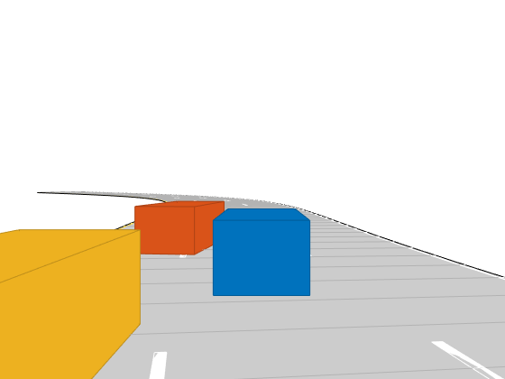
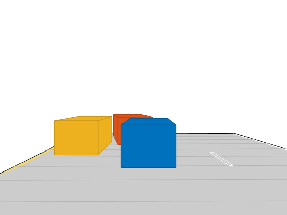
Display a chase plot from behind the ego vehicle for a 3D view of the scenario..

chasePlot(egovehicle)

Create Ultrasonic Sensors

Create an ultrasonic sensor mounted at the front of the ego vehicle.

frontUltrasonic = ultrasonicDetectionGenerator(1,FieldOfView=[70 35]);
frontUltrasonic.Profiles = actorProfiles(scenario);

Create a second ultrasonic sensor mounted on the left side of the ego vehicle.

leftUltrasonic = ultrasonicDetectionGenerator(2,MountingLocation=[0.5 1 0.2],MountingAngles=[90 0 0],FieldOfView=[70 35]);
leftUltrasonic.Profiles = actorProfiles(scenario);

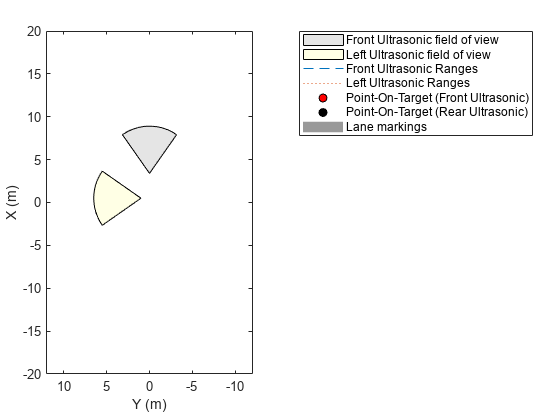
Create Bird's-Eye-Plot

Create a bird's-eye-plot for visualizing the sensor data. Add plotters for visualizing the ultrasonic coverage areas, detections, and points on targets. Use a rangeDetectionPlotter object to visualize ultrasonic detections as arcs and a detectionPlotter object to visualize the closest points on the target as markers. Add plotters to display the lane markings and vehicle outlines.

% Create bird's eye plot
bep = birdsEyePlot(XLim=[-20 20],YLim=[-12 12]);

% Plotters for Coverage areas of two ultrasonic sensors
fcaPlotter = coverageAreaPlotter(bep,DisplayName="Front Ultrasonic field of view");
plotCoverageArea(fcaPlotter,frontUltrasonic.MountingLocation(1:2), ...
  frontUltrasonic.DetectionRange(3),frontUltrasonic.MountingAngles(1),frontUltrasonic.FieldOfView(1));

lcaPlotter = coverageAreaPlotter(bep,DisplayName="Left Ultrasonic field of view",FaceColor="y");
plotCoverageArea(lcaPlotter,leftUltrasonic.MountingLocation(1:2), ...
  leftUltrasonic.DetectionRange(3),leftUltrasonic.MountingAngles(1),leftUltrasonic.FieldOfView(1));

% Range Detection Plotters for Ultrasonic Detections
frdPlotter = rangeDetectionPlotter(bep,DisplayName="Front Ultrasonic Ranges");
lrdPlotter = rangeDetectionPlotter(bep,DisplayName="Left Ultrasonic Ranges",LineStyle=":");

% Detection plotters for closest points on targets
fdetPlotter = detectionPlotter(bep,DisplayName="Point-On-Target (Front Ultrasonic)",MarkerFaceColor="r");
ldetPlotter = detectionPlotter(bep,DisplayName="Point-On-Target (Rear Ultrasonic)",MarkerFaceColor="k");

% Plotters for vehicle and target outlines, lane markings
olPlotter = outlinePlotter(bep);
lmPlotter = laneMarkingPlotter(bep,DisplayName="Lane markings");

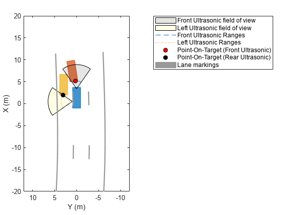
Run the Simulation and Generate Detections

Run the scenario simulation. At each timestep:

  1. Obtain the ground truth target poses, and generate detections for the two ultrasonic sensors.

  2. Obtain and display the target outlines and lane markings.

  3. When there are valid detections, display the detections and the corresponding points-on-targets generated by the ultrasonic sensor.

while advance(scenario)

    tgtpose = targetPoses(egovehicle);

    [fobdets,fisValid] = frontUltrasonic(tgtpose,scenario.SimulationTime);
    [lobdets,lisValid] = leftUltrasonic(tgtpose,scenario.SimulationTime);

    [objposition,objyaw,objlength,objwidth,objoriginOffset,color] = targetOutlines(egovehicle);
    plotOutline(olPlotter,objposition,objyaw,objlength,objwidth, ...
        OriginOffset=objoriginOffset,Color=color)

    [lmv,lmf] = laneMarkingVertices(egovehicle);
    plotLaneMarking(lmPlotter,lmv,lmf)

    if ~isempty(fobdets) && fisValid
        franges = fobdets{1}.Measurement;
        plotRangeDetection(frdPlotter,franges,frontUltrasonic.FieldOfView(1),frontUltrasonic.MountingLocation,frontUltrasonic.MountingAngles)
        plotDetection(fdetPlotter,fobdets{1}.ObjectAttributes{1}.PointOnTarget(1:2)')
    end

    if ~isempty(lobdets) && lisValid
        lranges = lobdets{1}.Measurement;
        plotRangeDetection(lrdPlotter,lranges,leftUltrasonic.FieldOfView(1),leftUltrasonic.MountingLocation,leftUltrasonic.MountingAngles)
        plotDetection(ldetPlotter,lobdets{1}.ObjectAttributes{1}.PointOnTarget(1:2)')
    end
end

Version History

Introduced in R2022a