RF Propagation and Visualization
RF propagation models describe the behavior of signals as they travel through the environment. You can display transmitter sites, receiver sites, and RF propagation visualizations by using Site Viewer, an interactive 3-D viewer. Site Viewer enables you to visualize propagation models in both outdoor and indoor environments.
Visualize Outdoor Wireless Coverage
Display transmitter and receiver sites on a 3-D globe, calculate the distance and angles between the sites, and analyze the signal strength of the transmitter at the receiver site. Display a communication link, a coverage map, and a signal-to-interference-plus-noise ratio (SINR) map.
Display Sites
Create a transmitter site and a receiver site. Specify the position using geographic coordinates in degrees.
tx = txsite("Latitude",42.3001,"Longitude",-71.3504);
rx = rxsite("Latitude",42.3021,"Longitude",-71.3764);
Display the sites in Site Viewer. Site Viewer displays geographic sites on an interactive 3-D globe. You can customize the propagation environment of the 3-D globe by using DTED terrain and OpenStreetMap® buildings.
show(tx)
show(rx)
Pan the map by clicking and dragging. Zoom out by using the scroll wheel.

Find Distance and Angles
Calculate the distance between the sites in meters. By default, the distance function calculates the distance along a straight line between the sites. This straight-line path is called the Euclidean path and ignores all obstructions, including the Earth.
dm = distance(tx,rx)
dm = 2.1556e+03
You can also calculate distance using a great circle path, which considers the curvature of the Earth.
Calculate the azimuth and elevation angles between the sites. For geographic sites, the angle function returns the azimuth angle in degrees, measured counterclockwise from the east. The angle function returns the elevation angle in degrees from the horizontal plane.
[az,el] = angle(tx,rx)
az = 174.0753
el = -0.7267
Analyze Signal Strength
The signal strength of a transmitter at a receiver site is given by the following equation:
where:
is the power available at the receiver.
is the transmitter output power.
is the transmitter gain.
= is the receiver gain.
pathloss is the RF attenuation suffered by the transmitter signal when it arrives at the receiver.
Calculate the signal strength at the desk receiver site. By default, the sigstrength function calculates signal strength in power units (dBm). You can also calculate the signal strength in electric field strength units (dBμV/m).
ss = sigstrength(rx,tx)
ss = -67.0767
The link margin measures the robustness of the communication link. Calculate the link margin by subtracting the required receiver sensitivity from the signal strength.
margin = abs(rx.ReceiverSensitivity - ss)
margin = 32.9233
Display Communication Link
Display the communication link status between the sites. The success of the link depends on the power received by the receiver from the transmitter. By default, a green line indicates that the received power meets or exceeds the receiver sensitivity. A red line indicates unsuccessful communication.
link(rx,tx)

Display Coverage Map
Display the coverage map of the transmitter. A coverage map visualizes the service area of the transmitter, which is where the received signal strength for a reference receiver meets its sensitivity. You can create coverage maps that depict signal strength as either a power quantity (typically dBm) or a voltage quantity (typically dBμV/m).
coverage(tx,"SignalStrengths",-100:5:-60) 
Find New Transmitter Site
Create and display a new transmitter site that is 1 km north of the existing transmitter site. Specify the antenna height as 30 m.
[lat,lon] = location(tx,1000,90);
tx2 = txsite("Latitude",lat,"Longitude",lon,"AntennaHeight",30);
show(tx2)

Calculate SINR
Calculate the SINR in decibels. The SINR of a receiver is given by the following equation:
where:
S is the received power of the signal of interest.
I is the received power of interfering signals in the network.
N is the total received noise power.
When Site Viewer has terrain data, the sinr function incorporates the terrain into the calculations.
sinr([tx,tx2])

Visualize Indoor Propagation Paths
Import a 3-D scene model of a conference room. Display sites and find propagation paths between the sites.
Import Scene
Import and view an STL file. The file models an indoor office with a conference room and open space separated by a partial wall. STL files contain geometry information and do not contain information about colors, surfaces, or textures.
viewer = siteviewer(SceneModel="office.stl",ShowOrigin=false);Display Sites
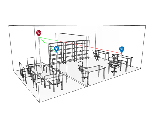
Place one transmitter near the ceiling in the conference room. Place one receiver on a desk in the open space and another receiver on a shelf. Specify the position using Cartesian coordinates in meters.
tx = txsite("cartesian",AntennaPosition=[2; 1.3; 2.5]);
rx_desk = rxsite("cartesian",AntennaPosition=[3.6; 7.5; 1]);
rx_shelf = rxsite("cartesian",AntennaPosition=[0.4; 3.3; 1]);
Display the receivers and the line-of-sight paths.
los(tx,[rx_desk rx_shelf])
Pan the scene by left-clicking, zoom by right-clicking or by using the scroll wheel, and rotate by clicking the middle button and dragging or by pressing Ctrl and left-clicking and dragging.

The path to the shelf receiver is clear and the path to the desk receiver is obstructed.
Display Propagation Paths
Create a ray tracing propagation model, which MATLAB® represents using a RayTracing object. Configure the model to use a Cartesian coordinate system and wooden surface materials. By default, the model uses the shooting and bouncing rays (SBR) method.
pm = propagationModel("raytracing", ...
    CoordinateSystem="cartesian", ...
    SurfaceMaterial="wood");
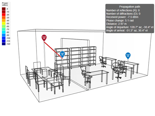
Display propagation paths that are within the line of sight by setting the MaxNumReflections property to 0. Unlike the los function, the raytrace function does not show obstructed paths.
pm.MaxNumReflections = 0;
clearMap(viewer)
raytrace(tx,[rx_desk rx_shelf],pm)

The raytrace function finds one line-of-sight path. You can view information about the path, such as the received power, by clicking on the path.
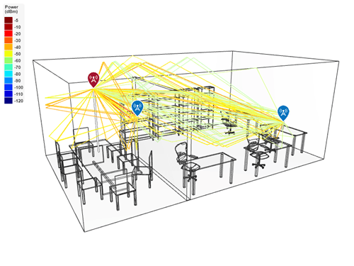
Display propagation paths with up to one reflection.
pm.MaxNumReflections = 1;
raytrace(tx,[rx_desk rx_shelf],pm)

Display propagation paths with up to one reflection and one diffraction.
pm.MaxNumDiffractions = 1;
raytrace(tx,[rx_desk rx_shelf],pm)

See Also
Functions
coverage|sigstrength|link|sinr|raytrace
Objects
siteviewer|txsite|rxsite