Main Content

M-PSK Modulator Baseband

Modulate using M-ary phase shift keying

  • M-PSK Modulator Baseband block

Libraries:
Communications Toolbox / Modulation / Digital Baseband Modulation / PM
Communications Toolbox HDL Support / Modulation / PM

Description

The M-PSK Modulator Baseband block modulates an input signal using M-ary phase shift keying (PSK) and returns a complex baseband output. The modulation order, M, which is equivalent to the number of points in the signal constellation, is determined by the M-ary number parameter. The block accepts scalar or column vector input signals.

Ports

Input

expand all

Specify the input signal as an integer scalar, integer vector, or binary vector.

  • When Input type is Integer, specify the input signal elements as integers from 0 to M – 1.

  • When Input type is Bit, specify the input signal as a binary vector in which the number of elements is an integer multiple of the bits per symbol. The bits per symbol is equal to log2(M).

Data Types: single | double | int8 | int16 | int32 | uint8 | uint16 | uint32 | Boolean

Output

expand all

Output signal, returned as a complex scalar or vector. The output is the complex baseband representation of the PSK-modulated signal.

Data Types: single | double | fixed point

Parameters

expand all

Specify the modulation order as a positive integer power of two.

Example: 2 | 16

Specify the elements of the input signal as integers or bits. If Input type is Bit, the number of samples per frame must be an integer multiple of the number of bits per symbol. The number of bits per symbol is log2(M).

Specify how the integer or group of log2(M) bits is mapped to the corresponding symbol.

  • When Constellation ordering is set to Gray, the input signal is mapped to the output symbols using a Gray-encoded signal constellation.

  • When Constellation ordering is set to Binary, the modulated symbol is exp(+j2πm/M), where ϕ is the phase offset in radians, m is the integer input such that 0 ≤ m ≤ M – 1, and M is the modulation order.

  • When Constellation ordering is User-defined, specify a vector of size M, which has unique integer values in the range [0, M–1]. The first element of this vector corresponds to the constellation point having an value of e with subsequent elements running counterclockwise.

Example: [0 3 2 1]

Specify the order in which input integers are mapped to output integers. The parameter is available when Constellation ordering is User-defined, and must be a row or column vector of size M having unique integer values in the range [0, M – 1].

The first element of this vector corresponds to the constellation point at 0 + Phase offset angle, with subsequent elements running counterclockwise. The last element corresponds to the -2π/M + Phase offset constellation point.

Specify, in radians, the phase offset of the initial constellation as a real scalar.

Example: pi/4

Specify the data type of the modulated output signal. Set this parameter to one of the fixed point options or <data type expression> to enable parameters in which you specify additional details. Set this parameter to Inherit via back propagation, to match the output data type and scaling to the following block in the model.

Block Characteristics

Data Types

Boolean | double | fixed pointa, b | integer | single

Multidimensional Signals

no

Variable-Size Signals

yes

a ufix(1) at the input if ''input type'' is set to ''bit''. ufix(ceil(log2(M))) at input if ''input type'' is set to ''integer'' for M-ary modulation.

b Fixed-point outputs must be signed.

More About

expand all

Algorithms

For binary-encoding, the output baseband signal maps input bits or integers to complex symbols according to:

sn(t)=exp(jπ(2n+1M));n{0,1,,M1}.

When the input is configured for bits, groups of log2(M) bits represent the complex symbols for the configured symbol mapping. The mapping can be binary encoded, Gray encoded, or custom encoded.

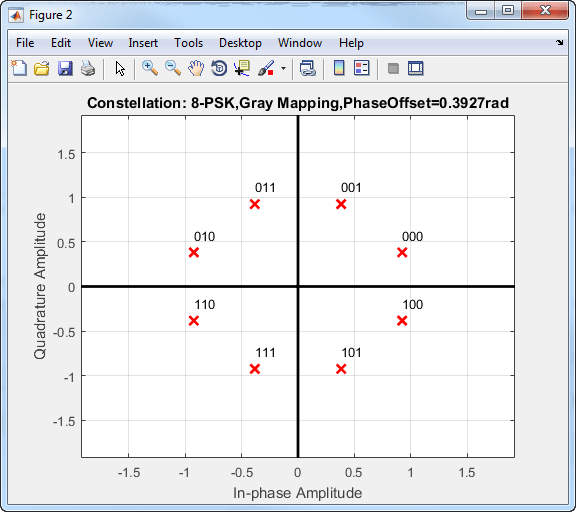
Gray coding has the advantage that only one bit changes between adjacent constellation points, which results in better bit error rate performance. This table shows the mapping between the input and output symbols for 8-PSK modulation with Gray coding.

InputOutput
0 0 (000)
1 1 (001)
2 3 (011)
3 2 (010)
4 6 (110)
5 7 (111)
6 5 (101)
7 4 (100)

This constellation diagram shows the corresponding symbols and their binary values.

Constellation diagram showing 8-PSK Gray Mapping with phase offset=0.3972 radians

References

[1] Proakis, John G. Digital Communications. 4th ed. New York: McGraw Hill, 2001.

Extended Capabilities

C/C++ Code Generation
Generate C and C++ code using Simulink® Coder™.

Version History

Introduced before R2006a