Integrate and Dump
Integrate discrete-time signal with periodic resets
Libraries:
Communications Toolbox /
Comm Filters
Description
The Integrate and Dump block creates a cumulative sum of the discrete-time input signal, while resetting the sum to zero according to a fixed schedule. When the simulation begins, the block discards the number of samples specified in the Offset (number of samples) parameter. After the initial offset, the block sums the input signal along columns and resets the sum to zero every N input samples, where N is the Integration period (number of samples) parameter value. The reset occurs after the block produces its output at that time step. For more information, see More About.
Receiver models often use the integrate-and-dump operation to receive simple square-pulse transmissions. Fiber optics and spread-spectrum communications systems also use the integrate-and-dump operation.
Examples
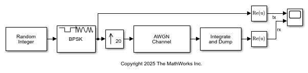
Apply the integrate-and-dump filter with an integration period of 20 samples to noisy random binary data.
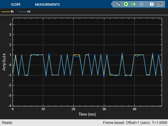
The cm_int_dump_filtering model upsamples BPSK modulated random binary data, adds noise to the data, and then applies integrate-and-dump filtering. A timescope plots the real component of samples for a frame of the transmitted random integer data (tx) and the received data after integrate and dump filtering (rx).


Ports
Input
Input signal, specified as a scalar, column vector, or matrix. Nonscalar input signals must consist of one or more columns with (k×N) rows. The block treats each column as an independent channel, performing integration along each column. k is a positive integer and N is the value of Integration period (number of samples).
This port is unnamed on the block.
Data Types: single | double | int8 | int16 | int32 | uint8 | uint16 | uint32 | Boolean
Output
Output signal, returned as a column vector or matrix. The number of rows in the output signal varies based on the value assigned to Output intermediate values parameter.
This port is unnamed on the block.
Parameters
To edit block parameters interactively, use the Property Inspector. From the Simulink® Toolstrip, on the Simulation tab, in the Prepare gallery, select Property Inspector.
Main
Number of input samples between resets, specified as an integer in the range [2, ∞).
Number of input samples to discard from each column of input data at the beginning of the simulation, specified as a nonnegative integer scalar or vector. When you set this parameter to a nonzero value, the block outputs zeros in place of the discarded initial input samples.
When you specify this parameter as a vector of length L, each element of the vector represents the number of samples to discard from the corresponding channel (column) of the input data matrix. The length of the vector L must match the number of columns in the input data matrix.
When you specify this property as a scalar value, the block applies the same offset value to each column of the input data matrix. The offset creates a transient effect, rather than a persistent delay.
Select this parameter to output intermediate cumulative sums between successive resets.
If you clear the check box (
off), then the block outputs the cumulative sum at each reset time.If the input is a scalar value, then the output sample time is N times the input sample time and the block experiences a delay whose duration is one output sample period. In this case, the output dimensions match the input dimensions.
If the input is a (k×N)-by-L matrix, then the output is k-by-L. In this case, the block experiences no delay and the output period matches the input period.
If you select the check box (
on), then the block outputs the cumulative sum at each time step. The output has the same sample time and the same matrix dimensions as the input.
Fixed-Point Attributes
The settings for the following parameters apply only when block inputs are fixed-point signals.
Data Types
Select the rounding mode for fixed-point operations. The block uses rounding mode when the result of a fixed-point calculation does not map exactly to a number representable by the data type. For more information, see Rounding Modes or Use Simplest Rounding for Efficient Generated Code (Fixed-Point Designer).
Use this parameter to specify the overflow mode to be used if the magnitude of a fixed-point calculation result does not fit into the range of the data type and scaling that stores the result.
When you clear the check box (
off), the fixed-point calculation wraps on overflow. The wrap uses modulo arithmetic to cast an overflow back into the representable range of the data type. For more information, see Modulo Arithmetic (Fixed-Point Designer).When you select the check box (
on), the fixed-point calculation saturates on overflow. The saturation represents positive overflows as the largest positive number in the range being used, and negative overflows as the largest negative number in the range being used.
Specify the accumulator word and fraction lengths. For diagrams showing the use of the accumulator data type in this block, see the filter structure diagrams for the Discrete FIR Filter (Simulink) block and Multiplication Data Types.
When you select
Inherit: Inherit via internal rule, the block inherits the data type based on an internal rule. For more information on this rule, see Inherit via Internal Rule.When you select
Inherit: Same as input, these characteristics match those of the input to the block.When you select
Binary point scaling, enter the word length and the fraction length of the output, in bits.
For information about specifying data types, see Data Type Assistant.
Specify the output word and fraction lengths.
When you select
Inherit: Same as input, these characteristics match those of the input to the block.When you select
Inherit: Same as accumulator, these characteristics match those of the accumulator.When you select
Binary point scaling, enter the word length and the fraction length of the output, in bits.
For information about specifying data types, see Data Type Assistant.
Block Characteristics
Data Types |
|
Multidimensional Signals |
|
Variable-Size Signals |
|
More About
A nonzero value in the Offset parameter causes the block to output one or more zeros during the initial period while it discards input samples. If the input is a matrix with n columns and the Offset parameter is a length-n vector, then the mth element of the Offset vector is the offset for the mth column of data. If Offset is a scalar, then the block applies the same offset to each column of data. The output of initial zeros due to a nonzero Offset value is a transient effect, not a persistent delay.
When you clear Output intermediate values, the block delays its output, relative to its input, throughout the simulation:
If the input is a scalar value, then the output is delayed by one sample after any transient effect is over. That is, after removing transients from the input and output, you can see the result of the mth integration period in the output sample indexed by m+1.
If the input is a column vector or matrix and the Offset parameter is nonzero, then after the transient effect is over, the result of each integration period appears in the output frame corresponding to the last input sample of that integration period. In cases where an integration period spans two input frames, the offset is one frame later than the output frame corresponding to the first input sample of that integration period.
This image illustrates a transient effect for three output samples and a one-sample delay for output samples from the block. The figure also indicates how the input and output values are organized as column vectors. For each vector in the figure:
Discarded input samples are white
Last samples of integration periods are underlined
Transient zeros in the output are white
.

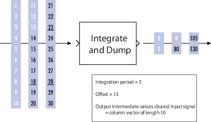
The transient effect lasts for ceil(13/5) output samples
because the block discards 13 input samples and the
integration period is 5. The first output sample after the
transient effect is over, 80, corresponds to the sum
14+15+16+17+18 and appears at the time of the input
sample 18. The next output sample, 105,
corresponds to the sum 19+20+21+22+23 and appears at the time
of the input sample 23. Notice that the input sample
23 is one frame later than the input sample
19; that is, this five-sample integration period spans
two input frames. As a result, the output of 105 is delayed
compared to the first input (19) that contributes to that
sum.
If you set Integration period
(number of samples) to 4 and Offset (number of
samples) to the scalar 3, this table shows the
block the first several output values for an input ramp signal
(1, 2, 3,
4, ...) depending on the Output
intermediate values check box setting and the input signal
properties. The values in the table do not reflect vector sizes but merely indicate
numerical values. In all cases, the block discards the first three input samples
(1, 2, and 3).
| Check Box | Input Signal Properties | First Several Output Values |
|---|---|---|
| Cleared | Scalar | 0, 0,
4+5+6+7, and 8+9+10+11,
where one 0 is an initial transient value and the
other 0 is a delay value that results from the
cleared check box and scalar value input. |
| Cleared | Column vector of length 4 | 0, 4+5+6+7, and
8+9+10+11, where 0 is an
initial delay value that results from the nonzero offset. The output
is a scalar value. |
| Selected | Scalar | 0, 0, 0,
4, 4+5,
4+5+6, 4+5+6+7,
8, 8+9,
8+9+10, 8+9+10+11, and
12, where the three 0s are
initial transient values. |
| Selected | Column vector of length 4
| 0, 0, 0,
4, 4+5,
4+5+6, 4+5+6+7,
8, 8+9,
8+9+10, 8+9+10+11, and
12, where the three 0s are
initial transient values. The output is a column vector of length
4. |

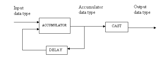
Floating-point inheritance takes precedence over the data type settings. When the block input is floating point, all block data types match the input. When the block input is fixed point, all internal data types are signed fixed point.
For more information about the parameters pertaining to fixed-point applications, see Specify Fixed-Point Attributes for Blocks.
The Data Type Assistant helps you set data
attributes. To use the Data Type Assistant, click
. For more information, see Specify Data Types Using Data Type Assistant (Simulink).
Extended Capabilities
C/C++ Code Generation
Generate C and C++ code using Simulink® Coder™.
Version History
Introduced before R2006a
See Also
Blocks
Objects
MATLAB Command
You clicked a link that corresponds to this MATLAB command:
Run the command by entering it in the MATLAB Command Window. Web browsers do not support MATLAB commands.
Select a Web Site
Choose a web site to get translated content where available and see local events and offers. Based on your location, we recommend that you select: .
You can also select a web site from the following list
How to Get Best Site Performance
Select the China site (in Chinese or English) for best site performance. Other MathWorks country sites are not optimized for visits from your location.
Americas
- América Latina (Español)
- Canada (English)
- United States (English)
Europe
- Belgium (English)
- Denmark (English)
- Deutschland (Deutsch)
- España (Español)
- Finland (English)
- France (Français)
- Ireland (English)
- Italia (Italiano)
- Luxembourg (English)
- Netherlands (English)
- Norway (English)
- Österreich (Deutsch)
- Portugal (English)
- Sweden (English)
- Switzerland
- United Kingdom (English)