DSB AM Modulator Passband
Modulate using double-sideband amplitude modulation
Libraries:
Communications Toolbox /
Modulation /
Analog Passband Modulation
Description
The DSB AM Modulator Passband block modulates a signal using double-sideband amplitude modulation.
Examples
Sample a 100 Hz input signal at 8000 samples per second. Modulate the input signal using the double-sideband amplitude modulation method with a Hilbert transform filter of order 100. Demodulate the signal. Plot the input signal, the modulated signal, and the demodulated signal.
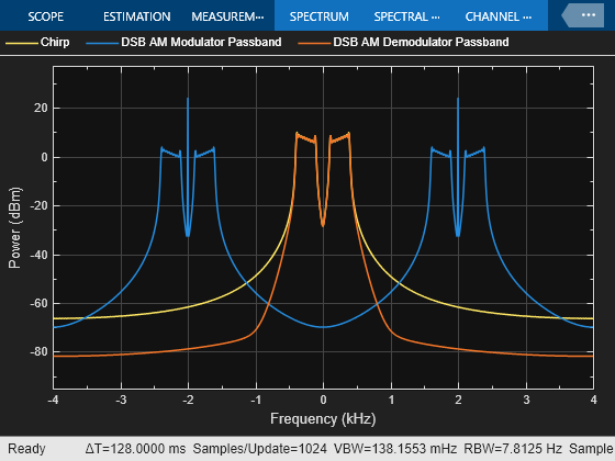
The dsb_moddemod_passband model modulates a signal using double-sideband amplitude modulation with a Hilbert transform filter and a carrier frequency of 2000 Hz and then demodulates the signal. When the model runs, it plots the signals. The model samples a 100 Hz linear frequency sweep chirp with a 400 Hz target frequency at 8000 samples per second. This configuration ensures the Hilbert transform filter operates in the flat section of the magnitude response and that the modulated signal has the desired magnitude and form.

Plot the input signal, the modulated sidebands, and the demodulated signal by using a spectrum analyzer.
Limitations
This block does not work inside a triggered subsystem.
Ports
Input
Output
Parameters
Block Characteristics
Data Types |
|
Multidimensional Signals |
|
Variable-Size Signals |
|
Algorithms
The DSB AM Modulator Passband block transmits the lower and upper sideband signal. For an input signal u(t), as a function of time t, the output is
where:
k represents the Input signal offset parameter.
fc represents the Carrier frequency (Hz) parameter.
θ represents the Initial phase (rad) parameter.
It is common to set the value of k to the maximum absolute value of the negative part of the input signal u(t).
Extended Capabilities
Version History
Introduced before R2006a