Main Content

DSB AM Demodulator Passband

Demodulate DSB-AM-modulated data

  • DSB AM Demodulator Passband block

Libraries:
Communications Toolbox / Modulation / Analog Passband Modulation

Description

The DSB AM Demodulator Passband block demodulates a signal that was modulated using double-sideband amplitude modulation. The block uses the envelope detection method. The input is a passband representation of the modulated signal. Both the input and output signals are real scalar signals.

Examples

expand all

Sample a 100 Hz input signal at 8000 samples per second. Modulate the input signal using the double-sideband amplitude modulation method with a Hilbert transform filter of order 100. Demodulate the signal. Plot the input signal, the modulated signal, and the demodulated signal.

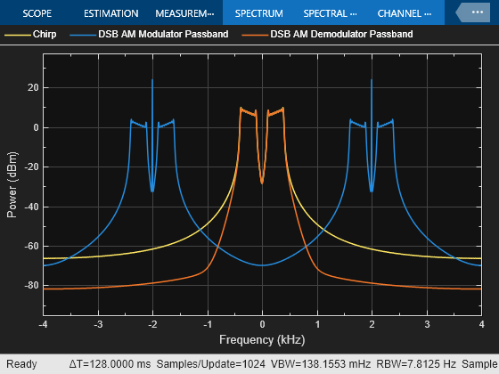
The dsb_moddemod_passband model modulates a signal using double-sideband amplitude modulation with a Hilbert transform filter and a carrier frequency of 2000 Hz and then demodulates the signal. When the model runs, it plots the signals. The model samples a 100 Hz linear frequency sweep chirp with a 400 Hz target frequency at 8000 samples per second. This configuration ensures the Hilbert transform filter operates in the flat section of the magnitude response and that the modulated signal has the desired magnitude and form.

Plot the input signal, the modulated sidebands, and the demodulated signal by using a spectrum analyzer.

Limitations

  • This block does not work inside a triggered subsystem.

Ports

Input

expand all

Input signal, specified as a scalar. The input is a passband representation of the modulated signal.

This port is unnamed on the block.

Data Types: double

Output

expand all

Demodulated output signal, returned as a scalar.

This port is unnamed on the block.

Data Types: double

Parameters

expand all

To edit block parameters interactively, use the Property Inspector. From the Simulink® Toolstrip, on the Simulation tab, in the Prepare gallery, select Property Inspector.

Input signal offset factor, k, specified as a scalar. This value should be greater than or equal to the absolute value of the minimum of the input signal. Set this parameter to the input signal offset value in the corresponding DSB AM Modulator Passband block.

Carrier frequency in Hz, specified as a positive scalar. Match the carrier frequency, fc, to the corresponding DSB AM Modulator Passband block.

Typically, an appropriate carrier frequency is a much higher than the highest frequency of the input signal. By the Nyquist sampling theorem, 1 / Ts > (2 × fc), where Ts represents the sample time of the input signal. For more information, see Baseband vs. Passband Simulation.

Initial phase offset of the carrier in radians, specified as a scalar.

Design method for the lowpass filter, specified as Butterworth Chebyshev type I, Chebyshev type II, or Elliptic.

Order of the lowpass filter, specified as a positive scalar in the range [1, 500]. This parameter value defines the order of the filter specified by the Lowpass filter design method parameter.

Cutoff frequency in Hz, specified as a positive scalar. This parameter value defines the cutoff frequency of the filter specified by the Lowpass filter design method parameter.

Peak-to-peak passband ripple in dB, specified as a positive scalar.

Dependencies

To enable this parameter, set Lowpass filter design method to Chebyshev type I or Elliptic.

Peak-to-peak stopband ripple in dB, specified as a positive scalar.

Dependencies

To enable this parameter, set Lowpass filter design method or Chebyshev type II or Elliptic.

Block Characteristics

Data Types

double

Multidimensional Signals

no

Variable-Size Signals

no

Version History

Introduced before R2006a