comm.SymbolSynchronizer
Correct symbol timing clock skew
Description
The comm.SymbolSynchronizer
System object™ corrects symbol timing clock skew between a
single-carrier transmitter and receiver for PAM, PSK, QAM, and OQPSK modulation schemes. For
more information, see Symbol Synchronization Overview.
Note
The input signal operates on a sample-rate basis and the output signal operates on a symbol-rate basis.
To correct symbol timing clock skew:
Create the
comm.SymbolSynchronizerobject and set its properties.Call the object with arguments, as if it were a function.
To learn more about how System objects work, see What Are System Objects?
Creation
Description
symbolSync = comm.SymbolSynchronizer
symbolSync = comm.SymbolSynchronizer(Name,Value)comm.SymbolSynchronizer('Modulation','OQPSK') configures the symbol
synchronizer System object for an OQPSK-modulated input signal. Enclose each property name in
quotes.
Tunable DampingFactor,
NormalizedLoopBandwidth, and DetectorGain
properties enable you to optimize synchronizer performance in your simulation loop without
releasing the object.
Properties
Usage
For versions earlier than R2016b, use the step
function to run the System object algorithm. The arguments to step are the
object you created, followed by the arguments shown in this section.
For example, y = step(obj,x) and y = obj(x) perform equivalent operations.
Description
symbols = symbolSync(samples)
The input operates on a sample-rate basis and the output signal operates on a symbol-rate basis.
You can tune the
DampingFactor,NormalizedLoopBandwidth, andDetectorGainproperties to improve the synchronizer performance.
Input Arguments
Output Arguments
Object Functions
To use an object function, specify the
System object as the first input argument. For
example, to release system resources of a System object named obj, use
this syntax:
release(obj)
Examples
Correct a fixed symbol timing error on a noisy QPSK-modulated signal. Check the bit error rate (BER) of the synchronized received signal.
Initialize simulation parameters.
M = 4;                % Modulation order for QPSK
nSym = 5000;          % Number of symbols in a packet
sps = 6;              % Samples per symbol
fracTimingErr = 0.3;  % Fractional part of timing error
snr = 15;             % Signal-to-noise ratio (dB)
Create root raised cosine (RRC) transmit and receive filter System objects.
txfilter = comm.RaisedCosineTransmitFilter( ...
    OutputSamplesPerSymbol=sps);
rxfilter = comm.RaisedCosineReceiveFilter( ...
    InputSamplesPerSymbol=sps, ...
    DecimationFactor=sps/2);
Create a symbol synchronizer System object to correct the timing error.
symbolSync = comm.SymbolSynchronizer
symbolSync =
  comm.SymbolSynchronizer with properties:

                 Modulation: 'PAM/PSK/QAM'
        TimingErrorDetector: 'Zero-Crossing (decision-directed)'
           SamplesPerSymbol: 2
              DampingFactor: 1
    NormalizedLoopBandwidth: 0.0100
               DetectorGain: 2.7000
Generate random M-ary symbols and apply QPSK modulation.
data = randi([0 M-1],nSym,1);
modSig = pskmod(data,M,pi/4);
Create a fractional delay filter to introduce a fixed fractional timing error of 0.3 samples. Because the transmit RRC filter outputs 4 samples per symbol, 1 sample is equivalent to a 1/4 symbol through the fixed delay and channel. Round the fixed delay down to the nearest integer symbol.
hFracDelay = designFracDelayFIR(FractionalDelay=fracTimingErr,Bandwidth=0.8);
fixedDelay = size(hFracDelay,2)/2 + fracTimingErr
fixedDelay =
11.3000
fixedDelaySym = ceil(fixedDelay/sps)
fixedDelaySym =
2
Filter the modulated signal through a transmit RRC filter by using the txfilter object. Apply a signal timing error by using the fixedDelay object.
txSig = txfilter(modSig);
delaySig = filter(hFracDelay,1,txSig);
Pass the delayed signal through an AWGN channel with a 15 dB signal-to-noise ratio.
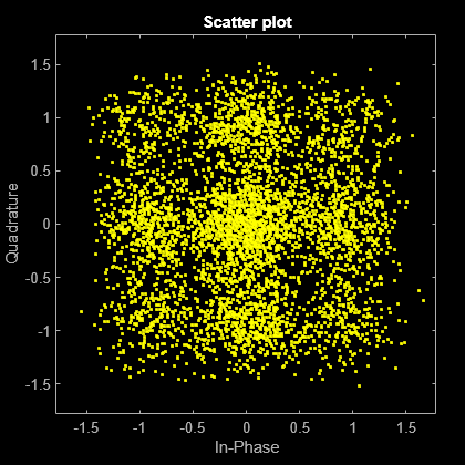
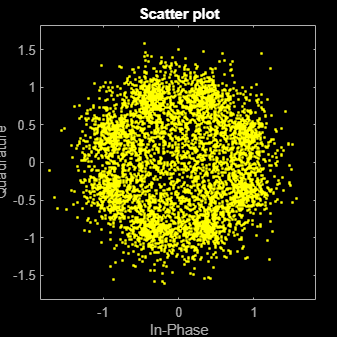
rxSig = awgn(delaySig,snr,'measured');Filter the modulated signal through a receive RRC filter by using the rxfilter object. Display the scatter plot. Due to the timing error, the received signal does not align with the expected QPSK reference constellation.
rxSample = rxfilter(rxSig);
scatterplot(rxSample(1001:end),2)
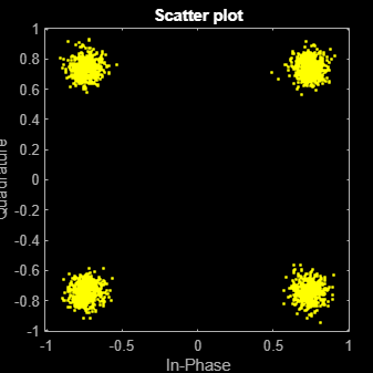
Correct the symbol timing error by using the symbolSync object. Display the scatter plot. The synchronized signal now aligns with the expected QPSK constellation.
rxSync = symbolSync(rxSample);
scatterplot(rxSync(1001:end),2)
Demodulate the QPSK signal.
recData = pskdemod(rxSync,M,pi/4);
Compute, in symbols, the total system delay due to the fixed delay and the transmit and receive RRC filters.
sysDelay = (fixedDelaySym + ...
    txfilter.FilterSpanInSymbols/2 + ...
    rxfilter.FilterSpanInSymbols/2);
Compute the BER, taking into account the system delay.
[numErr,ber] = biterr(data(1:end-sysDelay),recData(sysDelay+1:end))
numErr =
0
ber =
0
Correct a fixed symbol timing error on a noisy BPSK transmission signal. Check the bit error rate (BER) of the synchronized received signal.
Initialize simulation parameters.
M = 2;         % Modulation order for BPSK
nSym = 20000;  % Number of symbols in a packet
sps = 4;       % Samples per symbol
timingErr = 2; % Samples of timing error
snr = 15;      % Signal-to-noise ratio (dB)
Create root raised cosine (RRC) transmit and receive filter System objects.
txfilter = comm.RaisedCosineTransmitFilter( ...
    OutputSamplesPerSymbol=sps);
rxfilter = comm.RaisedCosineReceiveFilter( ...
    InputSamplesPerSymbol=sps,DecimationFactor=1);
Create a symbol synchronizer System object™ to correct the timing error.
symbolSync = comm.SymbolSynchronizer( ...
    SamplesPerSymbol=sps, ...
    NormalizedLoopBandwidth=0.01, ...
    DampingFactor=1.0, ...
    TimingErrorDetector='Early-Late (non-data-aided)');
Generate random data symbols and apply BPSK modulation.
data = randi([0 M-1],nSym,1);
modSig = pskmod(data,M);
Create a delay object to introduce a fixed timing error of 2 samples. Because the transmit RRC filter outputs 4 samples per symbol, 1 sample is equivalent to a 1/4 symbol through the fixed delay and channel. Round the fixed delay to the nearest integer symbol.
fixedDelay = dsp.Delay(timingErr);
fixedDelaySym = ceil(fixedDelay.Length/sps);
Filter the modulated signal through a transmit RRC filter by using the txfilter object. Apply a signal timing error by using the fixedDelay object.
txSig = txfilter(modSig);
delayedSig = fixedDelay(txSig);
Pass the delayed signal through an AWGN channel.
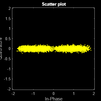
rxSig = awgn(delayedSig,snr,'measured');Filter the modulated signal through a receive RRC filter by using the rxfilter object. Display the scatter plot. Due to the timing error, the received signal does not align with the expected BPSK reference constellation.
rxSample = rxfilter(rxSig);
scatterplot(rxSample(10000:end),2)
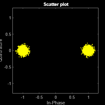
Correct the symbol timing error by using the symbolSync object. Display the scatter plot. The synchronized signal now aligns with the expected BPSK constellation.
rxSync = symbolSync(rxSample);
scatterplot(rxSync(10000:end),2)
Demodulate the BPSK signal.
recData = pskdemod(rxSync,M);
Compute, in symbols, the total system delay due to the fixed delay and the transmit and receive RRC filters.
sysDelay = dsp.Delay(fixedDelaySym + ...
    txfilter.FilterSpanInSymbols/2 + ...
    rxfilter.FilterSpanInSymbols/2);
Account for changes in output data length due to symbol synchronizer resampling and compute the BER, taking into account the system delay.
outLength = min(length(data),length(recData));
[numErr1,ber1] = biterr( ...
    sysDelay(data(1:outLength)),recData(1:outLength))
numErr1 = 6
ber1 =
3.0000e-04
Correct symbol timing and frequency offset errors by using the comm.SymbolSynchronizer and comm.CarrierSynchronizer System objects.
Configuration
Initialize simulation parameters.
M = 16;       % Modulation order
nSym = 2000;  % Number of symbols in a packet
sps = 2;      % Samples per symbol
spsFilt = 8;  % Samples per symbol for filters and channel
spsSync = 2;  % Samples per symbol for synchronizers
lenFilt = 10; % RRC filter length
Create a matched pair of root raised cosine (RRC) filter System objects for transmitter and receiver.
txfilter = comm.RaisedCosineTransmitFilter( ...
    FilterSpanInSymbols=lenFilt, ...
    OutputSamplesPerSymbol=spsFilt, ...
    Gain=sqrt(spsFilt));
rxfilter = comm.RaisedCosineReceiveFilter( ...
    FilterSpanInSymbols=lenFilt, ...
    InputSamplesPerSymbol=spsFilt, ...
    DecimationFactor=spsFilt/2, ...
    Gain=sqrt(1/spsFilt));
Create a phase-frequency offset System object to introduce a 100 Hz Doppler shift.
doppler = comm.PhaseFrequencyOffset( ...
    FrequencyOffset=100, ...
    PhaseOffset=45, ...
    SampleRate=1e6);
Create a variable delay System object to introduce timing offsets.
varDelay = dsp.VariableFractionalDelay;
Create carrier and symbol synchronizer System objects to correct for Doppler shift and timing offset, respectively.
carrierSync = comm.CarrierSynchronizer( ...
    SamplesPerSymbol=spsSync);
symbolSync = comm.SymbolSynchronizer( ...
    TimingErrorDetector='Early-Late (non-data-aided)', ...
    SamplesPerSymbol=spsSync);
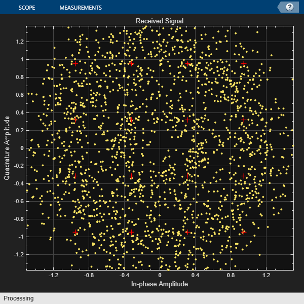
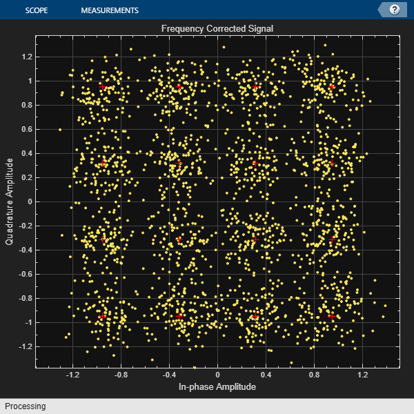
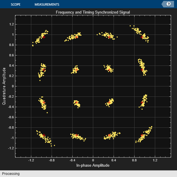
Create constellation diagram System objects to view the results.
refConst = qammod(0:M-1,M,UnitAveragePower=true);
cdReceive = comm.ConstellationDiagram( ...
    ReferenceConstellation=refConst, ...
    SamplesPerSymbol=spsFilt,Title='Received Signal');
cdDoppler = comm.ConstellationDiagram( ...
    ReferenceConstellation=refConst, ...
    SamplesPerSymbol=spsSync, ...
    Title='Frequency Corrected Signal');
cdTiming = comm.ConstellationDiagram( ...
    ReferenceConstellation=refConst, ...
    SamplesPerSymbol=spsSync, ...
    Title='Frequency and Timing Synchronized Signal');
Main Processing Loop
The main processing loop:
Generates random symbols and applies QAM modulation.
Filters the modulated signal.
Applies frequency and timing offsets.
Passes the transmitted signal through an AWGN channel.
Filters the received signal.
Corrects the Doppler shift.
Corrects the timing offset.
for k = 1:15
    data = randi([0 M-1],nSym,1);
    modSig = qammod(data,M,UnitAveragePower=true);
    txSig = txfilter(modSig);

    txDoppler = doppler(txSig);
    txDelay = varDelay(txDoppler,k/15);

    rxSig = awgn(txDelay,25);

    rxFiltSig = rxfilter(rxSig);
    rxCorr = carrierSync(rxFiltSig);
    rxData = symbolSync(rxCorr);
end
Visualization
Plot the constellation diagrams of the received signal, frequency corrected signal, and frequency and timing synchronized signal. Specific constellation points cannot be identified in the received signal and can be only partially identified in the frequency corrected signal. However, the timing and frequency synchronized signal aligns with the expected QAM constellation points.
cdReceive(rxSig)
cdDoppler(rxCorr)
cdTiming(rxData)
Correct a monotonically increasing symbol timing error on a noisy 8-PSK signal. Display the normalized timing error.
Initialize simulation parameters.
M = 8;            % Modulation order
nSym = 5000;      % Number of symbol in a packet
sps = 2;          % Samples per symbol
nSamp = sps*nSym; % Number of samples in a packet
Create root raised cosine (RRC) transmit and receive filter System objects.
txfilter = comm.RaisedCosineTransmitFilter( ...
    'OutputSamplesPerSymbol',sps);
rxfilter = comm.RaisedCosineReceiveFilter( ...
    'InputSamplesPerSymbol',sps, ...
    'DecimationFactor',1);
Create a variable fractional delay System object™ to introduce a monotonically increasing timing error.
varDelay = dsp.VariableFractionalDelay;
Create a symbol synchronizer System object to correct the timing error.
symbolSync = comm.SymbolSynchronizer(...
    'TimingErrorDetector','Mueller-Muller (decision-directed)', ...
    'SamplesPerSymbol',sps);
Generate random 8-ary symbols and apply 8-PSK modulation.
data = randi([0 M-1],nSym,1);
modSig = pskmod(data,M,pi/8);
Filter the modulated signal through a raised cosine transmit filter and apply a monotonically increasing timing delay.
vdelay = (0:1/nSamp:1-1/nSamp)';
txSig = txfilter(modSig);
delaySig = varDelay(txSig,vdelay);
Pass the delayed signal through an AWGN channel with a 15 dB signal-to-noise ratio.
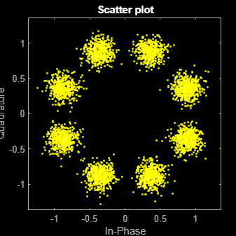
rxSig = awgn(delaySig,15,'measured');Filter the modulated signal through a receive RRC filter. Display the scatter plot. Due to the timing error, the received signal does not align with the expected 8-PSK reference constellation.
rxSample = rxfilter(rxSig);
scatterplot(rxSample,sps)
Correct the symbol timing error by using the symbolSync object. Display the scatter plot. The synchronized signal now aligns with the expected 8-PSK constellation.
[rxSym,tError] = symbolSync(rxSample);
scatterplot(rxSym(1001:end))
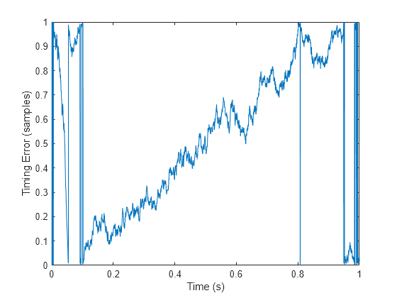
Plot the timing error estimate. Over time, the normalized timing error increases to 1 sample.
figure
plot(vdelay,tError)
xlabel('Time (s)')
ylabel('Timing Error (samples)')
Tips
Demodulate symbol-timing synchronized, OQPSK-modulated signals by using the
pskdemodfunction. You can not OQPSK demodulate the output of thecomm.SymbolSynchronizerSystem object because, for an OQPSK-modulated input signal, the object outputs a symbol-rate QPSK-modulated signal. Thecomm.OQPSKDemodulatorSystem object requires an OQPSK-modulated input signal with two samples per symbol.
Algorithms
The symbol timing synchronizer algorithm is based on a phased lock loop (PLL) algorithm that consists of four components:
Timing error detector (TED)
Interpolator
Interpolation controller
Loop filter
For OQPSK modulation, the in-phase and quadrature signal components are first aligned (as in QPSK modulation) using a state buffer to cache the last half symbol of the previous input. After initial alignment, the remaining synchronization process is the same as for QPSK modulation.
This block diagram shows an example of a timing synchronizer. In the figure, the symbol timing PLL operates on x(t), the received sample signal after matched filtering. The symbol timing PLL outputs the symbol signal, , after correcting for the clock skew between the transmitter and receiver.
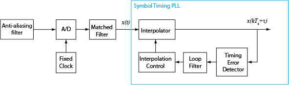
The time delay is estimated from the fixed-rate samples of the matched filter, which are asynchronous with the symbol rate. Because the resulting samples are not aligned with the symbol boundaries, an interpolator is used to "move" the samples. Because the time delay is unknown, the interpolator must be adaptive. Moreover, because the interpolant is a linear combination of the available samples, it can be thought of as the output of a filter.

The interpolator uses a piecewise parabolic interpolator with a Farrow structure and coefficient α set to 1/2 (see Rice, Michael, Digital Communications: A Discrete-Time Approach).
Interpolation control provides the interpolator with the basepoint index and fractional interval. The basepoint index is the sample index nearest to the interpolant. The fractional interval is the ratio of the time between the interpolant and its basepoint index and the interpolation interval.
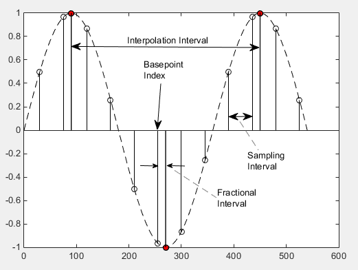
Interpolation is performed for every sample, and a strobe signal is used to determine if the interpolant is output. The synchronizer uses a modulo-1 counter interpolation control to provide the strobe and the fractional interval for use with the interpolator.
The synchronizer uses a proportional-plus integrator (PI) loop filter. The proportional gain, K1, and the integrator gain, K2, are calculated by
and
The interim term, θ, is given by
where:
Nsps is the number of samples per symbol.
ζ is the damping factor.
BnTs is the loop bandwidth (Bn) normalized to the symbol rate (Ts).
Kp is the detector gain.

References
[1] Rice, Michael. Digital Communications: A Discrete-Time Approach. Upper Saddle River, NJ: Prentice Hall, 2008.
[2] Mengali, Umberto and Aldo N. D’Andrea. Synchronization Techniques for Digital Receivers. New York: Plenum Press, 1997.
Extended Capabilities
Version History
Introduced in R2015a