comm.CarrierSynchronizer
Compensate for carrier frequency offset
Description
The comm.CarrierSynchronizer
System object™ compensates for carrier frequency and phase offsets in signals that use
single-carrier modulation schemes. The carrier synchronizer algorithm is compatible with BPSK,
QPSK, OQPSK, 8-PSK, PAM, and rectangular QAM modulation schemes.
Note
Modulation-type dependent phase ambiguities may be introduced by the synchronization algorithm. For more information, see Potential Phase Ambiguity.
To compensate for frequency and phase offsets in signals that use single-carrier modulation schemes:
Create the
comm.CarrierSynchronizerobject and set its properties.Call the object, as if it were a function.
To learn more about how System objects work, see What Are System Objects?.
Creation
Description
carrSynch = comm.CarrierSynchronizer
carrSynch = comm.CarrierSynchronizer(Name,Value)
Properties
Usage
Description
Input Arguments
Output Arguments
Object Functions
To use an object function, specify the
System object as the first input argument. For
example, to release system resources of a System object named obj, use
this syntax:
release(obj)
Examples
Correct phase and frequency offsets of a QPSK signal passed through an AWGN channel. Using preambles, resolve symbol phase ambiguity.
Define the simulation parameters.
M = 4;                             % Modulation order
rng(1993)                          % For repeatable results
barker = comm.BarkerCode( ...
    Length=13,SamplesPerFrame=13); % For preamble
msgLen = 1e4;
numFrames = 10;
frameLen = msgLen/numFrames;
Add preambles to each frame, which are used later when performing symbol phase ambiguity resolution. Generate random data symbols, and apply QPSK modulation.
preamble = (1+barker())/2;  % Length 13, unipolar
data = zeros(msgLen,1);
for idx = 1 : numFrames
    payload = randi([0 M-1],frameLen-barker.Length,1);
    data((idx-1)*frameLen + (1:frameLen)) = [preamble; payload];
end

modSig = pskmod(data,4,pi/4);
Create a comm.PhaseFrequencyOffset System object™ to introduce phase and frequency offsets to the modulated input signal. Set the phase offset to 45 degrees, frequency offset to 1 kHz, and sample rate to 10 kHz. The frequency offset is set to 1% of the sample rate.
pfo = comm.PhaseFrequencyOffset( ...
    PhaseOffset=45, ...
    FrequencyOffset=1e4, ...
    SampleRate=1e6);
Apply phase and frequency offsets using the pfo object, and then add white Gaussian noise.
modSigOffset = pfo(modSig);
rxSig = awgn(modSigOffset,12);
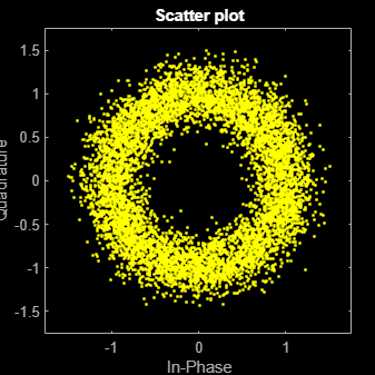
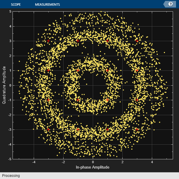
Display the scatter plot of the received signal. Due to the frequency offset, the data appears in a circle instead of being grouped around the reference constellation points.
scatterplot(rxSig)
Create a carrier synchronizer System object with samples per symbol set to 1. Use the carrierSync object to correct the phase and frequency offset in the received signal.
carrierSync = comm.CarrierSynchronizer( ...
    SamplesPerSymbol=1, ...
    Modulation='QPSK');
syncSignal = carrierSync(rxSig);
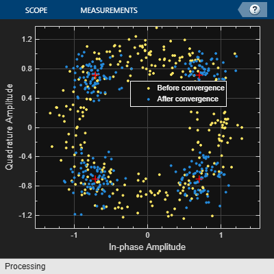
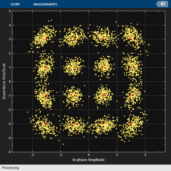
Use a constellation diagram to display the first and last 1000 symbols of the synchronized signal. Before convergence of the synchronizer loop, the plotted symbols are not grouped around the reference constellation points. After convergence, the plotted symbols are grouped around the reference constellation points.
constDiag = comm.ConstellationDiagram( ...
    SymbolsToDisplaySource='Property', ...
    SymbolsToDisplay=300, ...
    ChannelNames={'Before convergence','After convergence'}, ...
    ShowLegend=true, ...
    Position=[400 400 400 400]);

constDiag([syncSignal(1:1000) syncSignal(9001:10000)]);
Demodulate the synchronized signal. Compute and display the total symbol errors and SER.
syncData = pskdemod(syncSignal,4,pi/4);
[syncDataTtlErr,syncDataSER] = biterr( ...
    data(6000:end),syncData(6000:end))
syncDataTtlErr = 4000
syncDataSER =
0.4999
The carrier synchronizer object does not resolve symbol phase ambiguity. Symbol phase ambiguity in the received signal might cause symbol errors. Using the preamble, determine symbol phase ambiguity. Remove the symbol phase ambiguity from the synchronized signal to reduce symbol errors.
idx = 9000 + (1:barker.Length);
phOffset = angle(modSig(idx) .* conj(syncSignal(idx)));
phOffset = round((2/pi) * phOffset); % -1, 0, 1, +/-2
phOffset(phOffset==-2) = 2;          % Prep for mean operation
phOffset = mean((pi/2) * phOffset);  % -pi/2, 0, pi/2, or pi
disp(['Estimated mean phase offset = ', ...
    num2str(phOffset*180/pi),' degrees'])
Estimated mean phase offset = -90 degrees
resPhzSig = exp(1i*phOffset) * syncSignal;
Demodulate the signal after resolving the symbol phase ambiguity. Recompute and display the updated total symbol errors and SER. Removing the phase ambiguity reduces the SER dramatically.
resPhzData = pskdemod(resPhzSig,4,pi/4);
[resPhzTtlErr, resPhzSER] = biterr( ...
    data(6000:end),resPhzData(6000:end))
resPhzTtlErr = 3
resPhzSER =
3.7491e-04
Estimate the frequency offset introduced into a noisy 8-PSK signal using a carrier synchronizer System object™.
Define the simulation parameters.
M = 8;                  % Modulation order
fs = 1e6;               % Sample rate (Hz)
foffset = 1000;         % Frequency offset (Hz)
phaseoffset = 15;       % Phase offset (deg)
snrdb = 20;             % Signal-to-noise ratio (dB)
Create a comm.PhaseFrequencyOffset System object to introduce phase and frequency offsets to a modulated signal.
pfo = comm.PhaseFrequencyOffset('PhaseOffset',phaseoffset, ...
    'FrequencyOffset',foffset,'SampleRate',fs);
Create a carrier synchronizer System object to use for correcting the phase and frequency offsets. Set the Modulation property to 8PSK.
carrierSync = comm.CarrierSynchronizer('Modulation','8PSK');
Generate random data and apply 8-PSK modulation.
data = randi([0 M-1],5000,1);
modSig = pskmod(data,M,pi/M);
Apply phase and frequency offsets using the pfo System object, and pass the signal through an AWGN channel to add Gaussian white noise.
modSigOffset = pfo(modSig);
rxSig = awgn(modSigOffset,snrdb);
Use the carrier synchronizer to estimate the phase offset of the received signal.
[~,phError] = carrierSync(rxSig);
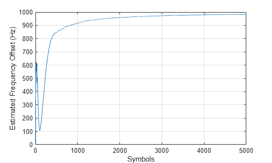
Determine the frequency offset by using the diff function to compute an approximate derivative of the phase error. The derivative must be scaled by because the phase error is measured in radians.
estFreqOffset = diff(phError)*fs/(2*pi);
Plot the running mean of the estimated frequency offset. After the synchronizer converges to a solution, the mean value of the estimate is approximately equal to the input frequency offset value of 1000 Hz.
rmean = cumsum(estFreqOffset)./(1:length(estFreqOffset))';
plot(rmean)
xlabel('Symbols')
ylabel('Estimated Frequency Offset (Hz)')
grid
Compensation of significant phase and frequency offsets for a 16-QAM signal in an AWGN channel is accomplished in two steps. First, correct the coarse frequency offset using the estimate provided by the coarse frequency compensator, and then fine-tune the correction using carrier synchronization. Because of the coarse frequency correction, the carrier synchronizer converges quickly even though the normalized bandwidth is set to a low value. Lower normalized bandwidth values enable better correction for small residual carrier offsets. After applying phase and frequency offset corrections to the received signal, resolve phase ambiguity using the preambles.
Define the simulation parameters.
fs = 10000;                  % Sample rate (Hz)
sps = 4;                     % Samples per symbol
M = 16;                      % Modulation order
k = log2(M);                 % Bits per symbol
rng(1996)                    % Set seed for repeatable results
barker = comm.BarkerCode(... % For preamble
    Length=13,SamplesPerFrame=13);
msgLen = 1e4;
numFrames = 10;
frameLen = msgLen/numFrames;
Generate data payloads and add the preamble to each frame. The preamble is later used for phase ambiguity resolution.
preamble = (1+barker())/2;  % Length 13, unipolar
data = zeros(msgLen, 1);
for idx = 1 : numFrames
    payload = randi([0 M-1],frameLen-barker.Length,1);
    data((idx-1)*frameLen + (1:frameLen)) = [preamble; payload];
end
Create a System object™ for the transmit pulse shape filtering, the receive pulse shape filtering, the QAM coarse frequency compensation, the carrier synchronization, and a constellation diagram.
txFilter = comm.RaisedCosineTransmitFilter( ...
    OutputSamplesPerSymbol=sps);
rxFilter = comm.RaisedCosineReceiveFilter(...
    InputSamplesPerSymbol=sps, ...
    DecimationFactor=sps);
coarse = comm.CoarseFrequencyCompensator( ...
    SampleRate=fs, ...
    FrequencyResolution=10);
fine = comm.CarrierSynchronizer( ...
    DampingFactor=0.4, ...
    NormalizedLoopBandwidth=0.001, ...
    SamplesPerSymbol=1, ...
    Modulation='QAM');
axislimits = [-6 6];
constDiagram = comm.ConstellationDiagram( ...
    ReferenceConstellation=qammod(0:M-1,M), ...
    ChannelNames={'Before convergence','After convergence'}, ...
    ShowLegend=true, ...
    AxesLimits=axislimits);
Also create a System object for the AWGN channel, and the phase and frequency offset to add impairments to the signal. A phase offset greater than 90 degrees is added to induce a phase ambiguity that results in a constellation quadrant shift.
ebn0 = 8;
freqoffset = 110;
phaseoffset = 110;
awgnChannel = comm.AWGNChannel( ...
    EbNo=ebn0, ...
    BitsPerSymbol=k, ...
    SamplesPerSymbol=sps);
pfo = comm.PhaseFrequencyOffset( ...
    FrequencyOffset=freqoffset, ...
    PhaseOffset=phaseoffset, ...
    SampleRate=fs);
Generate random data symbols, apply 16-QAM modulation, and pass the modulated signal through the transmit pulse shaping filter.
txMod = qammod(data,M);
txSig = txFilter(txMod);
Apply phase and frequency offsets using the pfo System object, and then pass the signal through an AWGN channel to add white Gaussian noise.
txSigOffset = pfo(txSig);
rxSig = awgnChannel(txSigOffset);
The coarse frequency compensator System object provides a rough correction for the frequency offset. For the conditions in this example, correcting the frequency offset of the received signal correction to within 10 Hz of the transmitted signal is sufficient.
syncCoarse = coarse(rxSig);
Pass the signal through the receive pulse shaping filter, and apply fine frequency correction.
rxFiltSig = fine(rxFilter(syncCoarse));
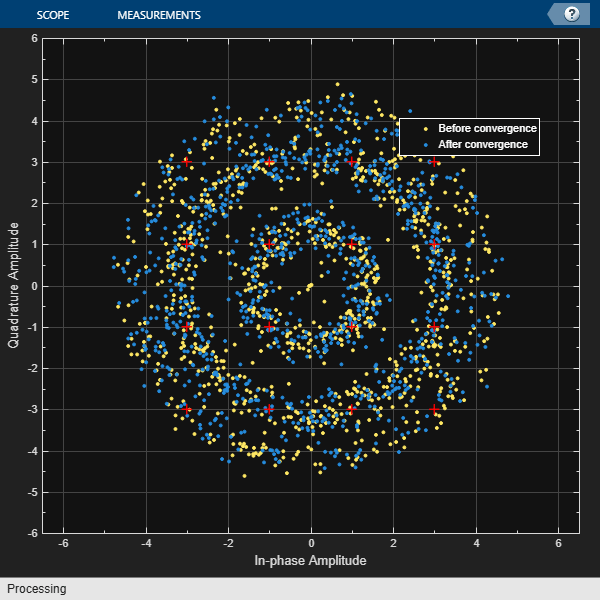
Display the constellation diagram of the first and last 1000 symbols in the signal. Before convergence of the synchronization loop, the spiral nature of the diagram indicates that the frequency offset is not corrected. After the carrier synchronizer has converged to a solution, the symbols are aligned with the reference constellation.
constDiagram([rxFiltSig(1:1000) rxFiltSig(9001:end)])
Demodulate the signal. Account for the signal delay caused by the transmit and receive filters to align the received data with the transmitted data. Compute and display the total bit errors and BER. When checking the bit errors, use the later portion of the received signal to be sure the synchronization loop has converged.
rxData = qamdemod(rxFiltSig,M);
delay = (txFilter.FilterSpanInSymbols + ...
    rxFilter.FilterSpanInSymbols) / 2;
idxSync = 2000; % Check BER after synchronization loop has converged
[syncDataTtlErr,syncDataBER] = biterr( ...
    data(idxSync:end-delay),rxData(idxSync+delay:end))
syncDataTtlErr =
13280
syncDataBER =
0.4155
Depending on the random data used, there may be bit errors resulting from phase ambiguity in the received signal after the synchronization loop converges and locks. In this case, you can use the preamble to determine and then remove the phase ambiguity from the synchronized signal to reduce bit errors. If phase ambiguity is minimal, the number of bit errors may be unchanged.
idx = 9000 + (1:barker.Length);
phOffset = angle(txMod(idx) .* conj(rxFiltSig(idx+delay)));

phOffsetEst = mean(phOffset);
disp(['Phase offset = ',num2str(rad2deg(phOffsetEst)),' degrees'])
Phase offset = -65.8162 degrees
resPhzSig = exp(1i*phOffsetEst) * rxFiltSig;
Demodulate the signal after resolving the phase ambiguity. Recompute the total bit errors and BER.
resPhzData = qamdemod(resPhzSig,M);
[resPhzTtlErr,resPhzBER] = biterr( ...
    data(idxSync:end-delay),resPhzData(idxSync+delay:end))
resPhzTtlErr = 13440
resPhzBER =
0.4205
Correct for a phase and frequency offset in a noisy QAM signal by using a carrier synchronizer. Then correct for the offsets using both a carrier synchronizer and a coarse frequency compensator.
Set the example parameters.
fs = 10000;   % Symbol rate (Hz)
sps = 4;      % Samples per symbol
M = 16;       % Modulation order
k = log2(M);  % Bits per symbol
EbNo = 20;    % Eb/No (dB)
SNR = convertSNR(EbNo,"ebno",BitsPerSymbol=k,SamplesPerSymbol=sps);
Create a constellation diagram object to visualize the effects of the offset compensation techniques. Specify the constellation diagram to display only the last 4000 samples.
constdiagram = comm.ConstellationDiagram( ...
    ReferenceConstellation=qammod(0:M-1,M), ...
    SamplesPerSymbol=sps, ...
    SymbolsToDisplaySource='Property', ...
    SymbolsToDisplay=4000, ...
    AxesLimits=[-5 5]);
Introduce a frequency offset of 400 Hz and a phase offset of 30 degrees.
phaseFreqOffset = comm.PhaseFrequencyOffset( ...
    FrequencyOffset=400, ...
    PhaseOffset=30, ...
    SampleRate=fs);
Generate random data symbols and apply 16-QAM modulation.
data = randi([0 M-1],10000,1);
modSig = qammod(data,M);
Create a raised cosine filter object and filter the modulated signal.
txfilter = comm.RaisedCosineTransmitFilter( ...
    OutputSamplesPerSymbol=sps, ...
    Gain=sqrt(sps));
txSig = txfilter(modSig);
Apply the phase and frequency offset, and then pass the signal through the AWGN channel.
freqOffsetSig = phaseFreqOffset(txSig);
rxSig = awgn(freqOffsetSig,SNR);
Apply fine frequency correction to the signal by using the carrier synchronizer.
fineSync = comm.CarrierSynchronizer( ...
    DampingFactor=0.7, ...
    NormalizedLoopBandwidth=0.005, ...
    SamplesPerSymbol=sps, ...
    Modulation='QAM');
rxData = fineSync(rxSig);
Display the constellation diagram of the last 4000 symbols.
constdiagram(rxData)
Even with time to converge, the spiral nature of the plot shows that the carrier synchronizer has not yet compensated for the large frequency offset. The 400 Hz offset is 1% of the sample rate.
Repeat the process with a coarse frequency compensator inserted before the carrier synchronizer.
Create a coarse frequency compensator to reduce the frequency offset to a manageable level.
coarseSync = comm.CoarseFrequencyCompensator( ...
    Modulation='QAM', ...
    FrequencyResolution=1, ...
    SampleRate=fs*sps);
Pass the received signal to the coarse frequency compensator and then to the carrier synchronizer.
syncCoarse = coarseSync(rxSig);
rxData = fineSync(syncCoarse);
Plot the constellation diagram of the signal after coarse and fine frequency compensation. The received data now aligns with the reference constellation.
constdiagram(rxData)
Correct symbol timing and frequency offset errors by using the comm.SymbolSynchronizer and comm.CarrierSynchronizer System objects.
Configuration
Initialize simulation parameters.
M = 16;       % Modulation order
nSym = 2000;  % Number of symbols in a packet
sps = 2;      % Samples per symbol
spsFilt = 8;  % Samples per symbol for filters and channel
spsSync = 2;  % Samples per symbol for synchronizers
lenFilt = 10; % RRC filter length
Create a matched pair of root raised cosine (RRC) filter System objects for transmitter and receiver.
txfilter = comm.RaisedCosineTransmitFilter( ...
    FilterSpanInSymbols=lenFilt, ...
    OutputSamplesPerSymbol=spsFilt, ...
    Gain=sqrt(spsFilt));
rxfilter = comm.RaisedCosineReceiveFilter( ...
    FilterSpanInSymbols=lenFilt, ...
    InputSamplesPerSymbol=spsFilt, ...
    DecimationFactor=spsFilt/2, ...
    Gain=sqrt(1/spsFilt));
Create a phase-frequency offset System object to introduce a 100 Hz Doppler shift.
doppler = comm.PhaseFrequencyOffset( ...
    FrequencyOffset=100, ...
    PhaseOffset=45, ...
    SampleRate=1e6);
Create a variable delay System object to introduce timing offsets.
varDelay = dsp.VariableFractionalDelay;
Create carrier and symbol synchronizer System objects to correct for Doppler shift and timing offset, respectively.
carrierSync = comm.CarrierSynchronizer( ...
    SamplesPerSymbol=spsSync);
symbolSync = comm.SymbolSynchronizer( ...
    TimingErrorDetector='Early-Late (non-data-aided)', ...
    SamplesPerSymbol=spsSync);
Create constellation diagram System objects to view the results.
refConst = qammod(0:M-1,M,UnitAveragePower=true);
cdReceive = comm.ConstellationDiagram( ...
    ReferenceConstellation=refConst, ...
    SamplesPerSymbol=spsFilt,Title='Received Signal');
cdDoppler = comm.ConstellationDiagram( ...
    ReferenceConstellation=refConst, ...
    SamplesPerSymbol=spsSync, ...
    Title='Frequency Corrected Signal');
cdTiming = comm.ConstellationDiagram( ...
    ReferenceConstellation=refConst, ...
    SamplesPerSymbol=spsSync, ...
    Title='Frequency and Timing Synchronized Signal');
Main Processing Loop
The main processing loop:
Generates random symbols and applies QAM modulation.
Filters the modulated signal.
Applies frequency and timing offsets.
Passes the transmitted signal through an AWGN channel.
Filters the received signal.
Corrects the Doppler shift.
Corrects the timing offset.
for k = 1:15
    data = randi([0 M-1],nSym,1);
    modSig = qammod(data,M,UnitAveragePower=true);
    txSig = txfilter(modSig);

    txDoppler = doppler(txSig);
    txDelay = varDelay(txDoppler,k/15);

    rxSig = awgn(txDelay,25);

    rxFiltSig = rxfilter(rxSig);
    rxCorr = carrierSync(rxFiltSig);
    rxData = symbolSync(rxCorr);
end
Visualization
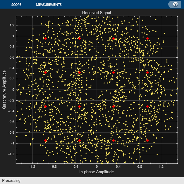
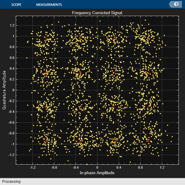
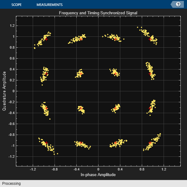
Plot the constellation diagrams of the received signal, frequency corrected signal, and frequency and timing synchronized signal. Specific constellation points cannot be identified in the received signal and can be only partially identified in the frequency corrected signal. However, the timing and frequency synchronized signal aligns with the expected QAM constellation points.
cdReceive(rxSig)
cdDoppler(rxCorr)
cdTiming(rxData)
Correct for a frequency offset by using the carrier synchronizer object. Increase the damping factor of the synchronizer and determine if the offset was corrected.
Set the modulation order, sample rate, frequency offset, and signal-to-noise ratio parameters.
M = 8;
fs = 1e6;
foffset = 1000;
snrdb = 20;
Create a phase frequency offset object to introduce a frequency offset to a modulated signal. Create a constellation diagram object.
pfo = comm.PhaseFrequencyOffset(SampleRate=fs, ...
    FrequencyOffset=foffset);
constDiagram = comm.ConstellationDiagram( ...
    ReferenceConstellation=pskmod(0:M-1,M,pi/M));
Create a carrier synchronizer object to correct for the frequency offset.
carriersync = comm.CarrierSynchronizer(Modulation='8PSK', ...
    DampingFactor=0.05,NormalizedLoopBandwidth=0.01);
The main processing loop includes these steps:
Generate random data.
Apply 8-PSK modulation.
Introduce a frequency offset.
Pass the signal through an AWGN channel.
Correct for the frequency offset.
Display the constellation diagram.
for k = 1:200
    data = randi([0 M-1],1000,1);
    modSig = pskmod(data,M);
    txSig = pfo(modSig);
    rxSig = awgn(txSig,snrdb);
    syncOut = carriersync(rxSig);
    constDiagram(syncOut)
end
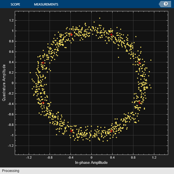
The constellation points cannot be clearly identified indicating that the carrier synchronizer is unable to compensate for the frequency offset.
Determine the normalized pull-in range, the maximum frequency lock delay, and the maximum phase lock delay by using the info function.
syncInfo = info(carriersync)
syncInfo = struct with fields:
    NormalizedPullInRange: 0.0044
    MaxFrequencyLockDelay: 78.9568
        MaxPhaseLockDelay: 130
Convert the normalized pull-in range from radians to cycles. Compare the normalized frequency offset to the pull-in range.
[foffset/fs syncInfo.NormalizedPullInRange/(2*pi)]
ans = 1×2
10-3 ×

    1.0000    0.7071
The offset is greater than the pull-in range. This is reason that the carrier synchronizer failed to correct the frequency offset.
Change the damping factor of the synchronizer to 0.707.
carriersync.DampingFactor = 0.707;
Repeat the main processing loop.
for k = 1:200
    data = randi([0 M-1],1000,1);
    modSig = pskmod(data,M);
    txSig = pfo(modSig);
    rxSig = awgn(txSig,snrdb);
    syncOut = carriersync(rxSig);
    constDiagram(syncOut)
end
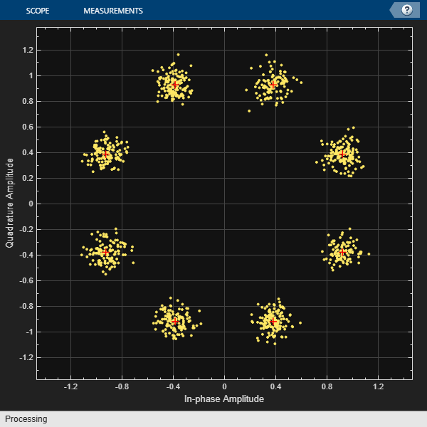
There are now eight observable clusters, which shows that the frequency offset was corrected.
Determine the new pull-in range. The normalized offset is less than the pull-in range. This explains why the carrier synchronizer was able to correct the offset.
syncInfo = info(carriersync);
[foffset/fs syncInfo.NormalizedPullInRange/(2*pi)]
ans = 1×2

    0.0010    0.0100
More About
Algorithms
The algorithm implements a closed-loop compensator that uses the PLL-based algorithm described in [1]. The output of the synchronizer, yn, is a frequency-shifted version of the complex input signal, xn, for the nth sample. The synchronizer output is where λn is the output of the direct digital synthesizer (DDS). The DDS is the discrete-time version of a voltage-controlled oscillator and is a core component of discrete-time phase locked loops. The DDS works as an integration filter.
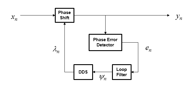
To correct for the frequency offset, first the algorithm determines the phase error, en. The value of the phase error depends on the modulation scheme.
| Modulation | Phase Error |
|---|---|
| QAM or QPSK | For a detailed description of this equation, see [1]. |
| BPSK or PAM | For a detailed description of this equation, see [1]. |
| 8-PSK | For a detailed description of this equation, see [2]. |
| OQPSK |
|
To ensure system stability, the phase error passes through a biquadratic loop filter governed by
where ψn is the output of the loop filter at sample n, and gI is the integrator gain. The integrator gain is determined from the equation
where
Bn is the normalized loop bandwidth
ζ is the damping factor
K0 is the phase recovery gain and equals the number of samples per symbol.
Kp is the phase error detector gain and is determined by the modulation type.
| Modulation | Kp |
|---|---|
| BPSK, PAM, QAM, QPSK, or OQPSK | 2 |
| 8-PSK | 1 |
The output of the loop filter is then passed to the DDS. The DDS is another biquadratic loop filter whose expression is based on the forward Euler integration rule
where gP is the proportional gain that is expressed as
The info object function returns estimates of the
normalized pull-in range, the maximum frequency lock delay, and the maximum phase lock
delay. The normalized pull-in range, (Δf)pull-in, is expressed in radians and estimated as
The expression for (Δf )pull-in becomes less accurate as approaches 1.
The maximum frequency lock delay, TFL, and phase lock delay, TPL, are expressed in samples and estimated as
References
[1] Rice, Michael. Digital Communications: A Discrete-Time Approach. Upper Saddle River, NJ: Prentice Hall, 2008. pp. 359–393.
[2] Huang Zhijie, Yi Zhiqiang, Zhang Ming and Wang Kuang, "8PSK demodulation for new generation DVB-S2," 2004 International Conference on Communications, Circuits and Systems (IEEE Cat. No.04EX914), Chengdu, 2004, pp. 1447-1450 Vol.2, doi: 10.1109/ICCCAS.2004.1346447.
Extended Capabilities
Version History
Introduced in R2015a