designVarSlopeFilter
Design variable slope lowpass or highpass IIR filter
Syntax
Description
[
specifies options using one or more B,A] =
designVarSlopeFilter(___,Name,Value)Name,Value pair
arguments.
Examples
Design two second-order section (SOS) lowpass IIR filters using designVarSlopeFilter.
Specify the sampling frequency, slope, and normalized cutoff frequency for two lowpass IIR filters. The sampling frequency is in Hz. The slope is in dB/octave.
Fs = 48e3;

slope = 18;

Fc1 = 10e3/(Fs/2);
Fc2 = 16e3/(Fs/2);
Design the filter coefficients using the specified parameters.
[B1,A1] = designVarSlopeFilter(slope,Fc1,"Orientation","row");
[B2,A2] = designVarSlopeFilter(slope,Fc2,"Orientation","row");
Visualize your filter design.
filterAnalyzer(B1,A1,B2,A2,SampleRates=Fs,FrequencyScale="log")
Design a second-order section (SOS) lowpass IIR filter using designVarSlopeFilter. Use your lowpass filter to process an audio signal.
Create audio file reader and audio device writer objects. Use the sample rate of the reader as the sample rate of the writer.
frameSize = 256;

fileReader = dsp.AudioFileReader( ...
    "RockGuitar-16-44p1-stereo-72secs.wav", ...
    SamplesPerFrame=frameSize);

sampleRate = fileReader.SampleRate;

deviceWriter = audioDeviceWriter( ...
    SampleRate=sampleRate);
Play the audio signal through your device.
count = 0;
while count < 2500
    audio = fileReader();
    deviceWriter(audio);
    count = count + 1;
end
reset(fileReader)
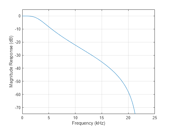
Design a lowpass filter with a 12 dB/octave slope and a 0.15 normalized cutoff frequency.
slope = 12;
cutoff = 0.15;
[B,A] = designVarSlopeFilter(slope,cutoff,Orientation="row");
Visualize your filter design.
[h,f] = freqz([B A],[],sampleRate);
plot(f/1000,mag2db(abs(h)))
grid
ylim([-75 5])
xlabel("Frequency (kHz)")
ylabel("Magnitude Response (dB)")

Create an SOS filter.
myFilter = dsp.SOSFilter(B,A);
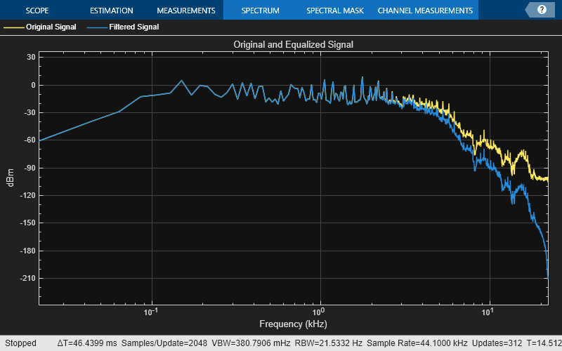
Create a spectrum analyzer to visualize the original audio signal and the audio signal passed through your lowpass filter.
scope = spectrumAnalyzer( ...
    SampleRate=sampleRate, ...
    PlotAsTwoSidedSpectrum=false, ...
    FrequencyScale="log", ...
    Title="Original and Equalized Signal", ...
    ShowLegend=true, ...
    ChannelNames={'Original Signal','Filtered Signal'});
Play the filtered audio signal and visualize the original and filtered spectrums.
count = 0;
while count < 2500
    originalSignal = fileReader();
    filteredSignal = myFilter(originalSignal);
    scope([originalSignal(:,1),filteredSignal(:,1)]);
    deviceWriter(filteredSignal);
    count = count + 1;
end
As a best practice, release your objects once done.
release(deviceWriter)
release(fileReader)
release(scope)

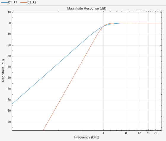
Design two second-order section (SOS) highpass IIR filters using designVarSlopeFilter.
Specify the sampling frequency in Hz, the slope in dB/octave, and the normalized cutoff frequency.
Fs = 48e3;
slope1 = 18;
slope2 = 36;
Fc = 4000/(Fs/2);
Design the filter coefficients using the specified parameters.
[B1,A1] = designVarSlopeFilter(slope1,Fc,"hi",Orientation="row");
[B2,A2] = designVarSlopeFilter(slope2,Fc,"hi",Orientation="row");
Visualize your filter design.
filterAnalyzer(B1,A1,B2,A2,...
       SampleRates=Fs,...
       FrequencyScale="log")

Plosives are consonant sounds resulting from a sudden release of airflow. They are most pronounced in words beginning with p, d, and g sounds. Plosives can be emphasized by the recording process and are often displeasurable to hear. In this example, you minimize the plosives of a speech signal by applying highpass filtering and low-band compression.
Create a dsp.AudioFileReader object and an audioDeviceWriter object to read an audio signal from a file and write an audio signal to a device. Play the unprocessed signal. Then release the file reader and device writer.
fileReader = dsp.AudioFileReader('audioPlosives.wav');
deviceWriter = audioDeviceWriter('SampleRate',fileReader.SampleRate);

while ~isDone(fileReader)
    audioIn = fileReader();
    deviceWriter(audioIn);
end
release(deviceWriter)
release(fileReader)
Design a highpass filter with a steep rolloff of all frequencies below 120 Hz. Use a dsp.SOSFilter object to implement the highpass filter design. Create a crossover filter with one crossover at 250 Hz. The crossover filter enables you to separate the band of interest for processing. Create a dynamic range compressor to compress the dynamic range of plosive sounds. To apply no make-up gain, set the MakeUpGainMode to "Property" and use the default 0 dB MakeUpGain property value. Create a time scope to visualize the processed and unprocessed audio signal.
[B,A] = designVarSlopeFilter(48,120/(fileReader.SampleRate/2),"hi",Orientation="row");
biquadFilter = dsp.SOSFilter(B,A);

crossFilt = crossoverFilter( ...
    "SampleRate",fileReader.SampleRate, ...
    "NumCrossovers",1, ...
    "CrossoverFrequencies",250, ...
    "CrossoverSlopes",48);

dRCompressor = compressor( ...
    "Threshold",-35, ...
    "Ratio",10, ...
    "KneeWidth",20, ...
    "AttackTime",1e-4, ...
    "ReleaseTime",3e-1, ...
    "MakeUpGainMode","Property", ...
    "SampleRate",fileReader.SampleRate);

scope = timescope( ...
    "SampleRate",fileReader.SampleRate, ...
    "TimeSpanSource","property","TimeSpan",3, ...
    "BufferLength",fileReader.SampleRate*3*2, ...
    "YLimits",[-1 1], ...
    "ShowGrid",true, ...
    "ShowLegend",true, ...
    "ChannelNames",{'Original','Processed'});
In an audio stream loop:
Read in a frame of the audio file.
Apply highpass filtering using your biquad filter.
Split the audio signal into two bands.
Apply dynamic range compression to the lower band.
Remix the channels.
Write the processed audio signal to your audio device for listening.
Visualize the processed and unprocessed signals on a time scope.
As a best practice, release your objects once done.
while ~isDone(fileReader)
    audioIn = fileReader();
    audioIn = biquadFilter(audioIn);
    [band1,band2] = crossFilt(audioIn);
    band1compressed = dRCompressor(band1);
    audioOut = band1compressed + band2;
    deviceWriter(audioOut);
    scope([audioIn audioOut])
end
As a best practice, release your objects once done.
release(deviceWriter)
release(fileReader)
release(crossFilt)
release(dRCompressor)
release(scope)

Input Arguments
Filter slope in dB/octave, specified as a real scalar in the range [0:6:48]. Values that are not multiples of 6 are rounded.
Data Types: single | double | int8 | int16 | int32 | int64 | uint8 | uint16 | uint32 | uint64
Normalized cutoff frequency, specified as a real scalar in the range 0 to 1, where 1 corresponds to the Nyquist frequency (π rad/sample).
Data Types: single | double | int8 | int16 | int32 | int64 | uint8 | uint16 | uint32 | uint64
Filter type, specified as 'lo' or 'hi'.
'lo'–– Lowpass filter'hi'–– Highpass filter
Data Types: char | string
Name-Value Arguments
Specify optional pairs of arguments as
Name1=Value1,...,NameN=ValueN, where Name is
the argument name and Value is the corresponding value.
Name-value arguments must appear after other arguments, but the order of the
pairs does not matter.
Before R2021a, use commas to separate each name and value, and enclose
Name in quotes.
Example: 'Orientation',"row"
Orientation of returned filter coefficients, specified as the
comma-separated pair consisting of 'Orientation' and
"column" or "row".
Data Types: char | string
Output Arguments
Numerator filter coefficients, returned as a matrix. The size and
interpretation of B depends on the
Orientation:
If
'Orientation'is set to"column", thenBis returned as a 3-by-4 matrix. Each column ofBcorresponds to the numerator coefficients of a different second-order section of your cascaded IIR filter.If
'Orientation'is set to"row", thenBis returned as a 4-by-3 matrix. Each row ofBcorresponds to the numerator coefficients of a different second-order section of your cascaded IIR filter.
Denominator filter coefficients, returned as a matrix. The size and interpretation of
A depends on the Orientation:
If
'Orientation'is set to"column", thenAis returned as a 2-by-4 matrix. Each column ofAcorresponds to the denominator coefficients of a different second-order section of your cascaded IIR filter.Adoes not include the leading unity coefficient for each section.If
'Orientation'is set to"row", thenBis returned as a 4-by-3 matrix. Each row ofBcorresponds to the denominator coefficients of a different second-order section of your cascaded IIR filter.
References
[1] Orfanidis, Sophocles J. "High-Order Digital Parametric Equalizer Design." Journal of the Audio Engineering Society. Vol. 53, November 2005, pp. 1026–1046.
Extended Capabilities
C/C++ Code Generation
Generate C and C++ code using MATLAB® Coder™.
Version History
Introduced in R2016aThe designVarSlopeFilter, designParamEQ, and designShelvingEQ functions will
return filter coefficients in row orientation by default in a future release. With
row orientation, the functions return the coefficients as matrices where each row
contains the coefficients of the corresponding second-order section of the
filter.
The default value of the Orientation name-value argument,
"column", will be removed in a future release and throws a
warning in R2024b. Set Orientation to "row"
to return coefficients in row orientation in the current release.
The designVarSlopeFilter, designParamEQ, and designShelvingEQ functions will
return filter coefficients in row orientation by default in a future release.
MATLAB Command
You clicked a link that corresponds to this MATLAB command:
Run the command by entering it in the MATLAB Command Window. Web browsers do not support MATLAB commands.
Select a Web Site
Choose a web site to get translated content where available and see local events and offers. Based on your location, we recommend that you select: .
You can also select a web site from the following list
How to Get Best Site Performance
Select the China site (in Chinese or English) for best site performance. Other MathWorks country sites are not optimized for visits from your location.
Americas
- América Latina (Español)
- Canada (English)
- United States (English)
Europe
- Belgium (English)
- Denmark (English)
- Deutschland (Deutsch)
- España (Español)
- Finland (English)
- France (Français)
- Ireland (English)
- Italia (Italiano)
- Luxembourg (English)
- Netherlands (English)
- Norway (English)
- Österreich (Deutsch)
- Portugal (English)
- Sweden (English)
- Switzerland
- United Kingdom (English)