802.11ac Packet Error Rate Simulation for 8x8 TGac Channel
This example shows how to measure the packet error rate of an IEEE® 802.11ac™ VHT link using an end-to-end simulation with a fading TGac channel model and additive white Gaussian noise.
Introduction
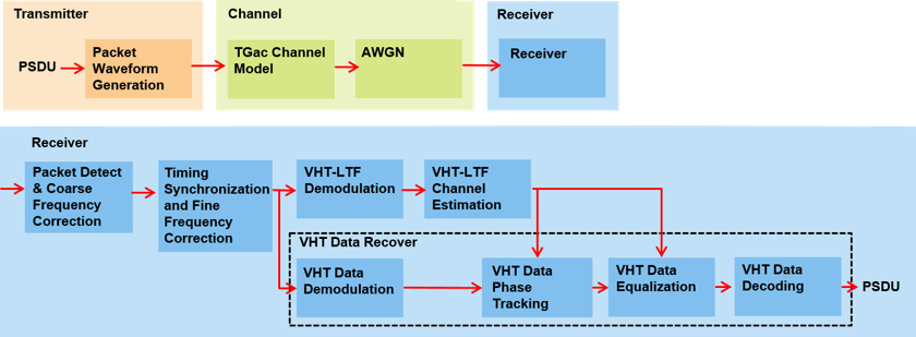
In this example an end-to-end simulation is used to determine the packet error rate for an 802.11ac [ 1 ] VHT link with a fading channel at a selection of SNR points. At each SNR point multiple packets are transmitted through a channel, demodulated and the PSDUs recovered. The PSDUs are compared to those transmitted to determine the number of packet errors and hence the packet error rate. Packet detection, timing synchronization, carrier frequency offset correction and phase tracking are performed by the receiver. The processing for each packet is summarized in the following
This example also demonstrates how a parfor loop can be used instead of the for loop when simulating each SNR point to speed up a simulation. The parfor function, as part of the Parallel Computing Toolbox™, executes processing for each SNR in parallel to reduce the total simulation time.
Waveform Configuration
An 802.11ac VHT transmission is simulated in this example. The VHT format configuration object, wlanVHTConfig, contains the format-specific configuration of the transmission. The properties of the object contain the configuration. In this example the object is configured for a 80 MHz channel bandwidth, 8 transmit antennas, 8 space-time streams, no space time block coding, 256-QAM rate-5/6 (MCS 9), and binary convolutional coding (BCC).
% Create a format configuration object for a 8-by-8 VHT transmission
cfgVHT = wlanVHTConfig;
cfgVHT.ChannelBandwidth = 'CBW80'; % 80 MHz channel bandwidth
cfgVHT.NumTransmitAntennas = 8;    % 8 transmit antennas
cfgVHT.NumSpaceTimeStreams = 8;    % 8 space-time streams
cfgVHT.APEPLength = 3000;          % APEP length in bytes
cfgVHT.MCS = 9;                    % 256-QAM rate-5/6
cfgVHT.ChannelCoding = 'BCC';      % Binary convolutional coding
Channel Configuration
In this example a TGac N-LOS channel model is used with delay profile Model-D. For Model-D when the distance between transmitter and receiver is greater than or equal to 10 meters, the model is NLOS. This is described further in wlanTGacChannel. An 8x8 MIMO channel is simulated in this example therefore 8 receive antennas are specified.
% Create and configure the channel
tgacChannel = wlanTGacChannel;
tgacChannel.DelayProfile = 'Model-D';
tgacChannel.NumReceiveAntennas = 8;
tgacChannel.TransmitReceiveDistance = 10; % Distance in meters for NLOS
tgacChannel.ChannelBandwidth = cfgVHT.ChannelBandwidth;
tgacChannel.NumTransmitAntennas = cfgVHT.NumTransmitAntennas;
tgacChannel.LargeScaleFadingEffect = 'None';
tgacChannel.NormalizeChannelOutputs = false;
Simulation Parameters
For each SNR point in the vector snr a number of packets are generated, passed through a channel and demodulated to determine the packet error rate.
snr = 40:5:50;
The number of packets tested at each SNR point is controlled by two parameters:
maxNumErrorsis the maximum number of packet errors simulated at each SNR point. When the number of packet errors reaches this limit, the simulation at this SNR point is complete.maxNumPacketsis the maximum number of packets simulated at each SNR point and limits the length of the simulation if the packet error limit is not reached.
The numbers chosen in this example will lead to a very short simulation. For meaningful results we recommend increasing the numbers.
maxNumErrors = 10;   % The maximum number of packet errors at an SNR point
maxNumPackets = 100; % The maximum number of packets at an SNR point
Set the remaining variables for the simulation.
% Get the baseband sampling rate
fs = wlanSampleRate(cfgVHT);

% Get the OFDM info
ofdmInfo = wlanVHTOFDMInfo('VHT-Data',cfgVHT);

% Set the sampling rate of the channel
tgacChannel.SampleRate = fs;

% Indices for accessing each field within the time-domain packet
ind = wlanFieldIndices(cfgVHT);
Processing SNR Points
For each SNR point a number of packets are tested and the packet error rate calculated.
For each packet the following processing steps occur:
A PSDU is created and encoded to create a single packet waveform.
The waveform is passed through a different realization of the TGac channel model.
AWGN is added to the received waveform to create the desired average SNR per active subcarrier after OFDM demodulation.
The packet is detected.
Coarse carrier frequency offset is estimated and corrected.
Fine timing synchronization is established. The L-STF, L-LTF and L-SIG samples are provided for fine timing to allow for packet detection at the start or end of the L-STF.
Fine carrier frequency offset is estimated and corrected.
The VHT-LTF is extracted from the synchronized received waveform. The VHT-LTF is OFDM demodulated and channel estimation is performed.
The VHT Data field is extracted from the synchronized received waveform. The PSDU is recovered using the extracted field and the channel estimate.
A parfor loop can be used to parallelize processing of the SNR points. To enable the use of parallel computing for increased speed comment out the for statement and uncomment the parfor statement below.
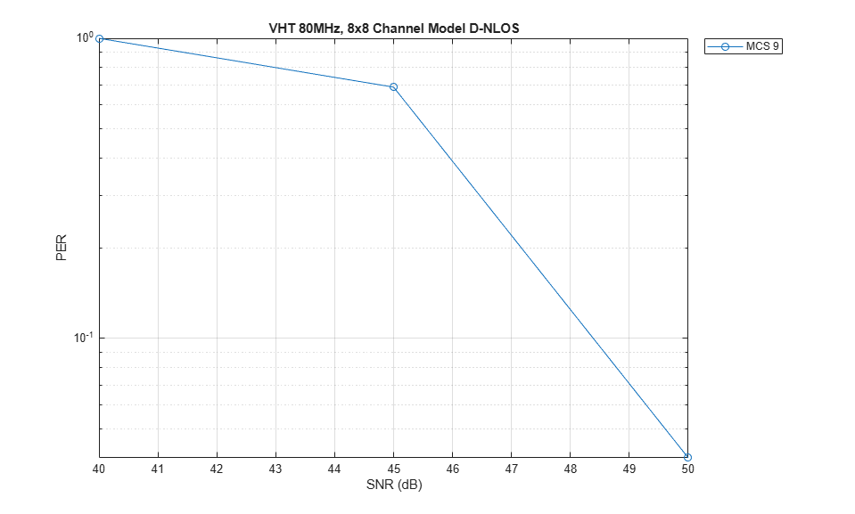
S = numel(snr);
packetErrorRate = zeros(S,1);
%parfor i = 1:S % Use 'parfor' to speed up the simulation
for i = 1:S     % Use 'for' to debug the simulation
    % Set random substream index per iteration to ensure that each
    % iteration uses a repeatable set of random numbers
    stream = RandStream('combRecursive',Seed=0);
    stream.Substream = i;
    RandStream.setGlobalStream(stream);

    % Account for noise energy in nulls so the SNR is defined per
    % active subcarrier
    packetSNR = snr(i)-10*log10(ofdmInfo.FFTLength/ofdmInfo.NumTones);

    % Loop to simulate multiple packets
    numPacketErrors = 0;
    numPkt = 1; % Index of packet transmitted
    while numPacketErrors<=maxNumErrors && numPkt<=maxNumPackets
        % Generate a packet waveform
        txPSDU = randi([0 1],cfgVHT.PSDULength*8,1); % PSDULength in bytes
        tx = wlanWaveformGenerator(txPSDU,cfgVHT);

        % Add trailing zeros to allow for channel delay
        tx = [tx; zeros(50,cfgVHT.NumTransmitAntennas)]; %#ok<AGROW>

        % Pass the waveform through the fading channel model
        reset(tgacChannel); % Reset channel for different realization
        rx = tgacChannel(tx);

        % Add noise
        rx = awgn(rx,packetSNR);

        % Packet detect and determine coarse packet offset
        coarsePktOffset = wlanPacketDetect(rx,cfgVHT.ChannelBandwidth);
        if isempty(coarsePktOffset) % If empty no L-STF detected; packet error
            numPacketErrors = numPacketErrors+1;
            numPkt = numPkt+1;
            continue; % Go to next loop iteration
        end

        % Extract L-STF and perform coarse frequency offset correction
        lstf = rx(coarsePktOffset+(ind.LSTF(1):ind.LSTF(2)),:);
        coarseFreqOff = wlanCoarseCFOEstimate(lstf,cfgVHT.ChannelBandwidth);
        rx = frequencyOffset(rx,fs,-coarseFreqOff);

        % Extract the non-HT fields and determine fine packet offset
        nonhtfields = rx(coarsePktOffset+(ind.LSTF(1):ind.LSIG(2)),:);
        finePktOffset = wlanSymbolTimingEstimate(nonhtfields,...
                    cfgVHT.ChannelBandwidth);

        % Determine final packet offset
        pktOffset = coarsePktOffset+finePktOffset;

        % If packet detected outwith the range of expected delays from the
        % channel modeling; packet error
        if pktOffset>50
            numPacketErrors = numPacketErrors+1;
            numPkt = numPkt+1;
            continue; % Go to next loop iteration
        end

        % Extract L-LTF and perform fine frequency offset correction
        lltf = rx(pktOffset+(ind.LLTF(1):ind.LLTF(2)),:);
        fineFreqOff = wlanFineCFOEstimate(lltf,cfgVHT.ChannelBandwidth);
        rx = frequencyOffset(rx,fs,-fineFreqOff);

        % Extract VHT-LTF samples from the waveform, demodulate and perform
        % channel estimation
        vhtltf = rx(pktOffset+(ind.VHTLTF(1):ind.VHTLTF(2)),:);
        vhtltfDemod = wlanVHTLTFDemodulate(vhtltf,cfgVHT);

        % Channel estimate
        [chanEst,chanEstSSPilots] = wlanVHTLTFChannelEstimate(vhtltfDemod,cfgVHT);

        % Extract VHT Data samples from the waveform
        vhtdata = rx(pktOffset+(ind.VHTData(1):ind.VHTData(2)),:);

        % Estimate the noise power in VHT data field
        nVarVHT = vhtNoiseEstimate(vhtdata,chanEstSSPilots,cfgVHT);

        % Recover the transmitted PSDU in VHT Data
        rxPSDU = wlanVHTDataRecover(vhtdata,chanEst,nVarVHT,cfgVHT,LDPCDecodingMethod='norm-min-sum',EarlyTermination=true);

        % Determine if any bits are in error, i.e. a packet error
        packetError = any(biterr(txPSDU,rxPSDU));
        numPacketErrors = numPacketErrors+packetError;
        numPkt = numPkt+1;
    end

    % Calculate packet error rate (PER) at SNR point
    packetErrorRate(i) = numPacketErrors/(numPkt-1);
    disp(['SNR ' num2str(snr(i)) ' completed after ' ...
        num2str(numPkt-1) ' packets, PER: ' ...
        num2str(packetErrorRate(i))]);
end
SNR 40 completed after 11 packets, PER: 1
SNR 45 completed after 16 packets, PER: 0.6875
SNR 50 completed after 100 packets, PER: 0.04
Plot Packet Error Rate vs SNR Results
figure
semilogy(snr,packetErrorRate,'-o');
grid on;
xlabel('SNR (dB)');
ylabel('PER');
legend('MCS 9','Location','NorthEastOutside')
title('VHT 80MHz, 8x8 Channel Model D-NLOS');
Further Exploration
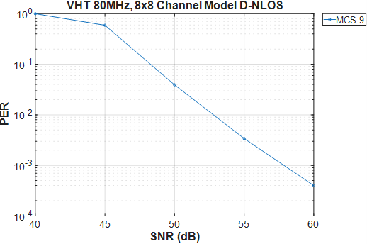
The number of packets tested at each SNR point is controlled by two parameters; maxNumErrors and maxNumPackets. For meaningful results it is recommend that these values should be larger than those presented in this example. Increasing the number of packets simulated allows the PER under different scenarios to be compared. Try changing the transmission and reception configurations and compare the packet error rate. As an example, the figure below was created by running the example for snr: 40:5:60, maxNumErrors: 1000 and maxNumPackets: 10000.
Selected Bibliography
IEEE Std 802.11™-2020. IEEE Standard for Information Technology - Telecommunications and Information Exchange between Systems - Local and Metropolitan Area Networks - Specific Requirements - Part 11: Wireless LAN Medium Access Control (MAC) and Physical Layer (PHY) Specifications.