Main Content

wlanHTSIG

Generate HT-SIG waveform

Description

example

y = wlanHTSIG(cfg) generates an HT-SIG1 time-domain waveform for an HT-mixed transmission parameterized by cfg.

example

[y,bits] = wlanHTSIG(cfg) also returns the information bits that comprise the HT-SIG field.

[___] = wlanHTSIG(cfg,OversamplingFactor=osf) generates an oversampled HT-SIG waveform with the specified oversampling factor. For more information about oversampling, see FFT-Based Oversampling.

Examples

collapse all

Generate an HT-SIG waveform for a single transmit antenna.

Create an HT configuration object. Specify a 40 MHz channel bandwidth.

cfg = wlanHTConfig;
cfg.ChannelBandwidth = 'CBW40'
cfg = 
  wlanHTConfig with properties:

       ChannelBandwidth: 'CBW40'
    NumTransmitAntennas: 1
    NumSpaceTimeStreams: 1
         SpatialMapping: 'Direct'
                    MCS: 0
          GuardInterval: 'Long'
          ChannelCoding: 'BCC'
             PSDULength: 1024
         AggregatedMPDU: 0
     RecommendSmoothing: 1

Generate the HT-SIG waveform. Determine the size of the waveform.

y = wlanHTSIG(cfg);
size(y)
ans = 1×2

   320     1

The function returns a waveform having a complex output of 320 samples corresponding to two 160-sample OFDM symbols.

Generate an HT-SIG waveform and display the MCS information. Change the MCS and display the updated information.

Create a wlanHTConfig object having two spatial streams and two transmit antennas. Specify an MCS value of 8, corresponding to BPSK modulation and a coding rate of 1/2.

cfg = wlanHTConfig('NumSpaceTimeStreams',2,'NumTransmitAntennas',2,'MCS',8);

Generate the information bits from the HT-SIG waveform.

[~,sigBits] = wlanHTSIG(cfg);

Extract the MCS field from sigBits and convert it to its decimal equivalent. The MCS information is contained in bits 1-7.

mcsBits = sigBits(1:7);
bit2int(mcsBits,7,false)
ans = int8
    8

The MCS matches the specified value.

Change the MCS to 13, which corresponds to 64-QAM modulation with a 2/3 coding rate. Generate the HT-SIG waveform.

cfg.MCS = 13;
[~,sigBits] = wlanHTSIG(cfg);

Verify that the MCS bits are the binary equivalent of 13.

mcsBits = sigBits(1:7);
bit2int(mcsBits,7,false)
ans = int8
    13

Input Arguments

collapse all

Transmission parameters, specified as a wlanHTConfig object.

Oversampling factor, specified as a scalar greater than or equal to 1. The oversampled cyclic prefix length must be an integer number of samples.

Data Types: single | double | int8 | int16 | int32 | int64 | uint8 | uint16 | uint32 | uint64

Output Arguments

collapse all

HT-SIG waveform, returned as an NS-by-NT matrix. NS is the number of time-domain samples, and NT is the number of transmit antennas.

Data Types: double
Complex Number Support: Yes

HT-SIG information bits, returned as a 48-by-1 vector.

Data Types: int8

More About

collapse all

HT-SIG

The high throughput signal (HT-SIG) field is located between the L-SIG field and HT-STF and is part of the HT-mixed format preamble. It is composed of two symbols, HT-SIG1 and HT-SIG2.

The HT-SIG field in the HT-mixed preamble

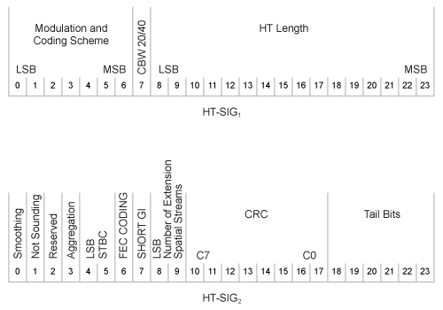
HT-SIG carries information used to decode the HT packet, including the MCS, packet length, FEC coding type, guard interval, number of extension spatial streams, and whether there is payload aggregation. The HT-SIG symbols are also used for auto-detection between HT-mixed format and legacy OFDM packets.

Packet structure of HT-SIG1 and HT-SIG2

For a detailed description of the HT-SIG field, see section 19.3.9.4.3 of IEEE® Std 802.11™-2020.

HT-mixed

As described in IEEE Std 802.11-2012, Section 20.1.4, high throughput mixed (HT-mixed) format packets contain a preamble compatible with IEEE Std 802.11-2012, Section 18 and Section 19 receivers. Non-HT (Section 18 and Section19) STAs can decode the non-HT fields (L-STF, L-LTF, and L-SIG). The remaining preamble fields (HT-SIG, HT-STF, and HT-LTF) are for HT transmission, so the Section 18 and Section 19 STAs cannot decode them. The HT portion of the packet is described in IEEE Std 802.11-2012, Section 20.3.9.4. Support for the HT-mixed format is mandatory.

Algorithms

collapse all

FFT-Based Oversampling

An oversampled signal is a signal sampled at a frequency that is higher than the Nyquist rate. WLAN signals maximize occupied bandwidth by using small guardbands, which can pose problems for anti-imaging and anti-aliasing filters. Oversampling increases the guardband width relative to the total signal bandwidth, thereby increasing the number of samples in the signal.

This function performs oversampling by using a larger IFFT and zero pad when generating an OFDM waveform. This diagram shows the oversampling process for an OFDM waveform with NFFT subcarriers comprising Ng guardband subcarriers on either side of Nst occupied bandwidth subcarriers.

FFT-based oversampling

References

[1] IEEE Std 802.11™-2012 IEEE Standard for Information technology — Telecommunications and information exchange between systems — Local and metropolitan area networks — Specific requirements — Part 11: Wireless LAN Medium Access Control (MAC) and Physical Layer (PHY) Specifications.

Extended Capabilities

C/C++ Code Generation
Generate C and C++ code using MATLAB® Coder™.

Version History

Introduced in R2015b


1 IEEE Std 802.11-2012 Adapted and reprinted with permission from IEEE. Copyright IEEE 2012. All rights reserved.