HDL Implementation of Digital Predistorter
This example shows the implementation of a digital predistorter (DPD) model that is optimized for HDL code generation and hardware implementation. The predistortion mechanism is executed in two stages. In the first stage, a set of DPD coefficients are estimated based on the input and output data of the power amplifier (PA). In the second stage, the input data of the PA is predistorted based on the estimated DPD coefficients and provided as new input to the PA. This example demonstrates a system-level simulation in which the Digital Predistorter subsystem generates HDL code, while the DPD coefficient estimation generates C/C++ code. This example model supports only Normal and Accelerator simulation modes.
Digital Predistortion
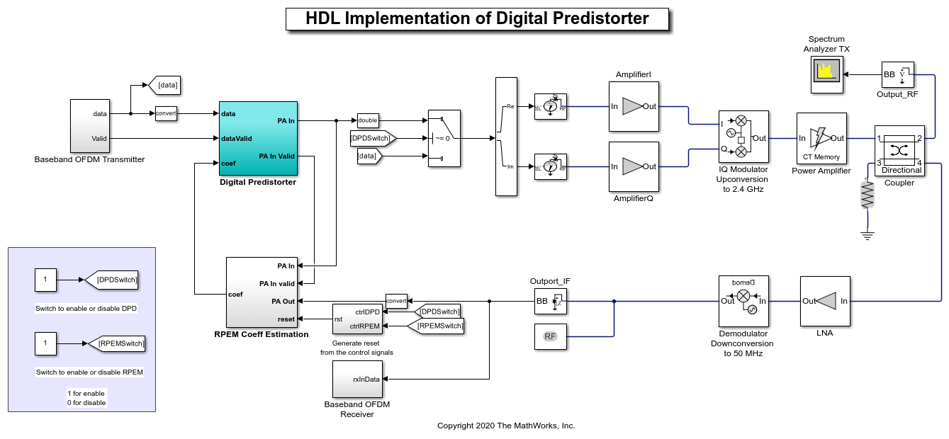
Digital predistortion is a baseband signal processing technique that is used for correcting impairments in radio frequency (RF) power amplifiers. These impairments cause out-of-band emissions or spectral regrowth and in-band distortion, which results in an increased bit error rate (BER) and a decreased throughput of the system. Power amplifiers cause unwanted effects in the system due to their nonlinear behavior. Communication systems using orthogonal frequency division multiplexing (OFDM), such as a wireless local area network (WLAN), worldwide interoperability for microwave access (WiMax), long term evolution (LTE), and 5G new radio (NR), are vulnerable to these unwanted effects. A precorrection is applied on the signal so that the cascade of the DPD and PA is close to an ideal, linear, and memoryless system. This linearization can improve PA power efficiency and can be more spectrum efficient. This figure shows the top-level structure of the example.
Run this command to open the example.
modelname = 'DPDHDLExample';
open_system(modelname);
Baseband OFDM Transmitter
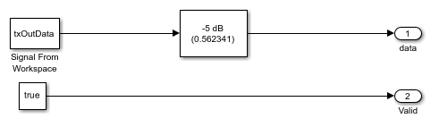
The Baseband OFDM Transmitter subsystem generates a baseband signal and provides that signal as input data to the Digital Predistorter subsystem. The OFDMTx function in this subsystem generates an OFDM transmitter waveform with synchronization, reference, header, pilots, and data signals and returns txWaveform, txGrid, and diagnostics using the transmitter parameter set txParam. For more information about the OFDMTx function, see the HDL OFDM MATLAB References example. You can also replace the Baseband OFDM Transmitter subsystem with any custom transmitter to provide data to the Digital Predistorter subsystem. This figure shows the baseband input signal generation for this example. Run this command to open the Baseband OFDM Transmitter subsystem.
load_system(modelname);
open_system([modelname '/Baseband OFDM Transmitter']);
Coefficients Estimation
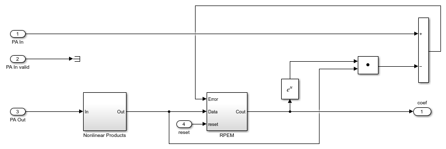
The RPEM Coeff Estimation subsystem estimates a set of coefficients by collecting data from the input and output of the PA. These coefficients are used to distort the signal before the power amplifier. PA characteristics vary over time and operating conditions, so an adaptive recursive prediction error method (RPEM) algorithm is used to estimate the DPD coefficients. The number of coefficients to be estimated depends on the memory depth and polynomial degree of the PA. In this example, because the total number of coefficients that need to be estimated is 25, the memory depth and polynomial degree of the PA are set to 5. For more information about the RPEM, see [ 1 ]. To generate C/C++ code for RPEM Coeff Estimation subsystem, use the slbuild command. Run this command to open the RPEM Coeff Estimation subsystem.
load_system(modelname);
open_system([modelname '/RPEM Coeff Estimation']);
Digital Predistorter
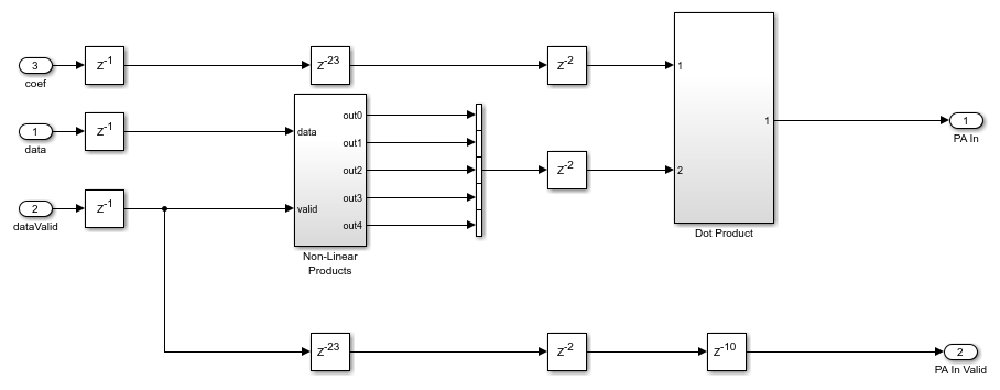
The Digital Predistorter subsystem distorts the input data using the coefficients estimated by the RPEM Coeff Estimation subsystem. The DPD design in this example is based on a memory polynomial, which corrects the nonlinearities and memory effects in the PA. The estimated coefficients and the generated input data are provided as input to the DPD for applying predistortion. The input data is first placed in a shift register based on the memory depth. Second, this vector is concatenated with the nonlinear products of the data depending on the polynomial degree. This concatenation forms a vector of 25 that means memory depth times degree elements. The dot product of the obtained vector and estimated coefficients provides the predistorted input that is fed as input to PA after upsampling. Run this command to open the Digital Predistorter subsystem.
load_system(modelname);
open_system([modelname '/Digital Predistorter']);
RF Blocks Configuration
This example has a control switch to enable or disable predistortion and coefficient estimation. If you enable the switch, the example provides the output data from the Digital Predistorter subsystem as input to RF blocks. Otherwise, the example provides the output data from the Baseband OFDM Transmitter subsystem as input to RF blocks as in-phase (I), quadrature-phase (Q) samples. These I/Q samples are upsampled to 2.4 GHz and provided as input to the PA. The coefficient matrix required by the PA is preloaded based on the standard-compliant LTE signal with a sample rate of 15.36 MHz. These coefficients are stored in a MAT file, and the values are loaded while initializing the example. In the other path, the data is passed through a low noise amplifier (LNA) and is down-converted before providing it to the RPEM Coeff Estimation subsystem.
Baseband OFDM Receiver
The Baseband OFDM Receiver subsystem collects the down-converted data and provides it as an input to the OFDMRx function. This function performs carrier frequency offset estimation and correction, frame synchronization, OFDM demodulation, channel estimation, channel equalization, phase offset correction, and decodes the transmitted bits. For more information about the OFDMRx function, see the HDL OFDM MATLAB References example.
Verification and Results
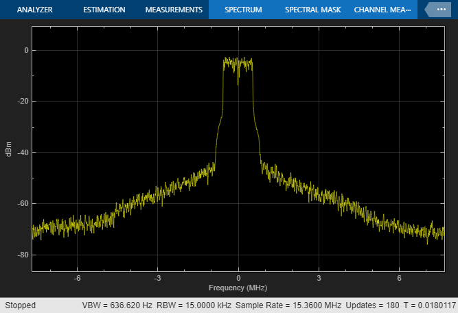
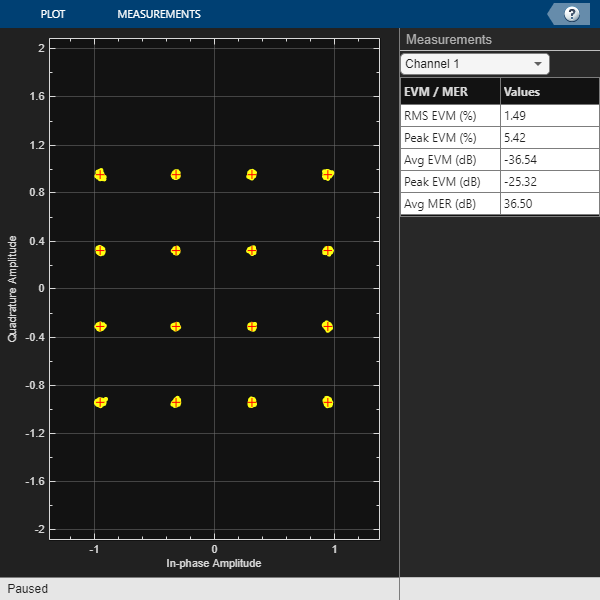
Run the model. By default, the Digital Predistorter and RPEM Coeff Estimation are enabled. If you disable the DPD, the error vector magnitude (EVM) increases, and the spectral regrowth in adjacent channels increases. The constellation and spectrum analyzer diagrams show the results of running the model with the DPD enabled.
sim(modelname);
 Estimating carrier frequency offset ...

 First four frames are used for carrier frequency offset estimation.

 Estimated carrier frequency offset is -5.497154e+00 Hz.

 Detected and processing frame 5
------------------------------------------

 Header CRC passed

 Modulation: 16QAM, codeRate=1/2 and FFT Length=128

 Data CRC passed

 Data decoding completed
------------------------------------------

 Detected and processing frame 6
------------------------------------------

 Header CRC passed

 Modulation: 16QAM, codeRate=1/2 and FFT Length=128

 Data CRC passed

 Data decoding completed
------------------------------------------
HDL Code Generation and Implementation Results
To check and generate HDL for this example, you must have HDL Coder™. Use the makehdl and makehdltb commands to generate the HDL code and test bench for the Digital Predistorter subsystem.
The Digital Predistorter subsystem is synthesized on a Xilinx® Zynq®-7000 ZC706 evaluation board. The frequency obtained after place and route is about 220 MHz. Create a table that displays the post place and route resource utilization results for a 16-bit complex input.
F = table(...
    categorical({'Slice LUT'; 'Slice Registers';'DSP'}), ...
    categorical({'6028'; '8115'; '160'}), ...
    categorical({'218600'; '437200'; '900'}), ...
    categorical({'2.75'; '1.85'; '17.78'}), ...
    'VariableNames', ...
    {'Resources','Utilized','Available','Utilization (%)'});
disp(F);
       Resources       Utilized    Available    Utilization (%)
    _______________    ________    _________    _______________

    Slice LUT            6028       218600           2.75
    Slice Registers      8115       437200           1.85
    DSP                  160        900              17.78
References
1. Gan, Li, and Emad Abd-Elrady. ''Digital Predistortion of Memory Polynomial Systems Using Direct and Indirect Learning Architectures.'' In Proceedings of the Eleventh IASTED International Conference on Signal and Image Processing (SIP) (F. Cruz-Roldan and N. B. Smith, eds.), No. 654-802. Calgary, AB: ACTA Press, 2009.