Main Content

WLAN LDPC Decoder

Decode LDPC code according to WLAN standard

Since R2021b

  • WLAN LDPC Decoder block

Libraries:
Wireless HDL Toolbox / Error Detection and Correction

Description

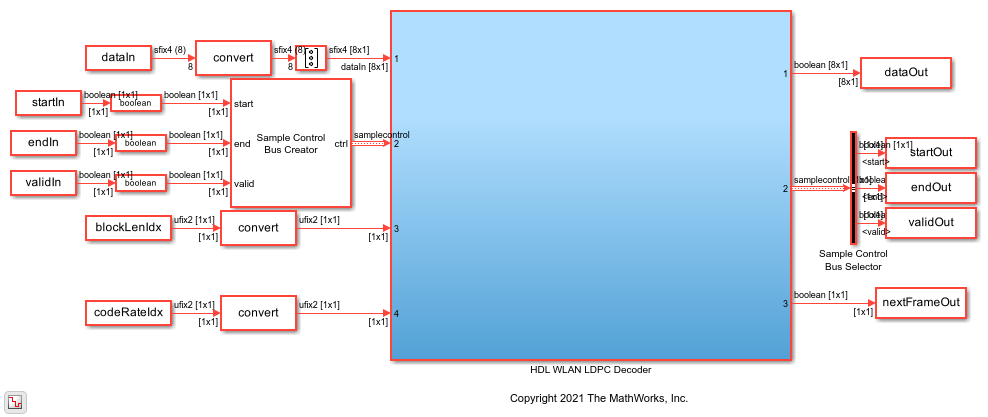
The WLAN LDPC Decoder block implements a low-density parity-check (LDPC) decoder using a layered belief propagation with min-sum approximation and normalized min-sum approximation algorithms for decoding LDPC codes according to the wireless local area network (WLAN) standards IEEE® 802.11n™, 802.11ac™, 802.11ax™, and 802.11ad™. The block accepts log-likelihood ratio (LLR) values, a stream of control signals, a block length, and a code rate as inputs and outputs decoded bits, a stream of control signals, and a signal that indicates when the block is ready to accept new inputs.

The WLAN LPDC Decoder block supports scalar inputs and vector inputs. The block supports early termination to help improve decoding performance and convergence speeds at high signal-noise-ratio (SNR) conditions. For more information about WLAN standards, see [1], [2], and [3].

The block provides an architecture suitable for HDL code generation and hardware deployment. You can use this block in the WLAN modem development.

Examples

Ports

Input

expand all

LLR values, specified as a scalar or a vector of size 8-by-1.

For HDL code generation, specify this value in signed fixed point format. The input word length must be in the range from 4 to 16.

Data Types: int8 | int16 | signed fixed point

Control signals accompanying the sample stream, specified as a samplecontrol bus. The bus includes the start, end, and valid control signals, which indicate the boundaries of the frame and the validity of the samples.

  • start — Indicates the start of the input frame

  • end — Indicates the end of the input frame

  • valid — Indicates that the data on the input data port is valid

For more details, see Sample Control Bus.

Data Types: bus

Block length index, specified as 0, 1, or 2. The block length varies based on the specified block length index.

This table shows the block length index values and their corresponding block lengths.

blkLenIdx ValueBlock Length
0 648
11296
21944

When you specify a value other than 0, 1, or 2, the block discards the frame and sets the nextFrame output port to 1.

Dependencies

To enable this port, set the Standard parameter to IEEE 802.11 n/ac/ax.

Data Types: fixdt(0,2,0)

Code rate index, specified as 0, 1, 2, or 3. The code rate varies based on the standard and code rate index that you specify.

This table shows the code rate index values and their corresponding code rates based on the standard.

Standard Parameter ValuecodeRateIdx ValueCode Rate
IEEE 802.11 n/ac/ax0 1/2
12/3
23/4
35/6
IEEE 802.11 ad0 1/2
15/8
23/4
313/16

Data Types: fixdt(0,2,0)

Number of iterations, specified as an unsigned integer in the range from 1 to 63.

If you specify an iter value greater than 63 or less than 1, the block overrides your specification and sets the iter value to 8 before decoding.

Dependencies

To enable this port, set the Decoding termination criteria parameter to Max and the Source for number of iterations parameter to Input port.

Data Types: uint8

Output

expand all

Decoded bits, returned as a Boolean scalar or a Boolean vector of size 8-by-1.

For a vector input, if the output data length is not a multiple of 8, the block appends zeros at the end of the output to make it as a multiple of 8.

For example, when you set the Standard parameter to IEEE 802.11 n/ac/ax, the blkLenIdx input port to 0, and the codeRateIdx input port to 2, instead of the block returning the 486 samples, the block appends two zeros to the 486 samples to make it as a multiple of 8. In this case, the block returns 488 samples in 61 (488/8) clock cycles.

Data Types: Boolean

Control signals accompanying the sample stream, returned as a samplecontrol bus. The bus includes the start, end, and valid control signals, which indicate the boundaries of the frame and the validity of the samples.

  • start — Indicates the start of the output frame

  • end — Indicates the end of the output frame

  • valid — Indicates that the data on the output data port is valid

For more details, see Sample Control Bus.

Data Types: bus

Block ready indicator, returned as a Boolean scalar.

The block sets this signal to 1 (true) when the block is ready to accept the start of the next frame. If the block receives an input ctrl.start signal while nextFrame is 0 (false), the block discards the frame in progress and begins processing the new data.

Data Types: Boolean

Actual number of iterations the block takes to decode the output, returned as a scalar.

Dependencies

To enable this port, set the Decoding termination criteria parameter to Early.

Data Types: uint8

Parity check status indicator, returned as a Boolean scalar. The port indicates the status of the parity check after the decoding operation.

  • 0 — Indicates that the parity check failed

  • 1 — Indicates that the parity check passed

Dependencies

To enable this port, select the Enable parity check output port parameter.

Data Types: Boolean

Parameters

expand all

Select the type of standard. For more information, see [1], [2], and [3].

When you set the Standard parameter to IEEE 802.11 ad, the blkLenIdx input port is disabled and the block considers a fixed block length of 672 for its operation.

Select the type of LDPC decoding algorithm. For more information, see Algorithm.

  • Min-sum — Use this option to select the layered belief propagation algorithm with a min-sum approximation. For more information, see Min-Sum Approximation.

  • Normalized min-sum — Use this option to select the layered belief propagation algorithm with a normalized min-sum approximation. For more information, see Normalized Min-Sum Approximation.

Specify the scaling factor as scalar in the range from 0.5 to 1, incremented by 0.0625.

Dependencies

To enable this parameter, set the Algorithm parameter to Normalized min-sum.

Select the decoding termination criteria.

  • Max — Terminate decoding when the block reaches the number of iterations specified in the block mask or through the iter input port.

  • Early — Terminate decoding when the block meets all of the parity checks or when the block reaches the maximum number of iterations provided in the block mask.

Select the source for specifying the number of iterations.

You can set the number of iterations by using either an input port or a parameter.

  • Property — Select this option to enable the Number of iterations parameter.

  • Input port — Select this option to enable the iter port.

Dependencies

To enable this parameter, set the Decoding termination criteria parameter to Max.

Specify the number of decoding iterations.

Dependencies

To enable this parameter, set the Decoding termination criteria parameter to Max and the Source for number of iterations parameter to Property.

Specify the maximum number of decoding iterations.

Dependencies

To enable this parameter, set the Decoding termination criteria parameter to Early.

Select this parameter to enable the parityCheck output port to view the status of the parity check.

Algorithms

expand all

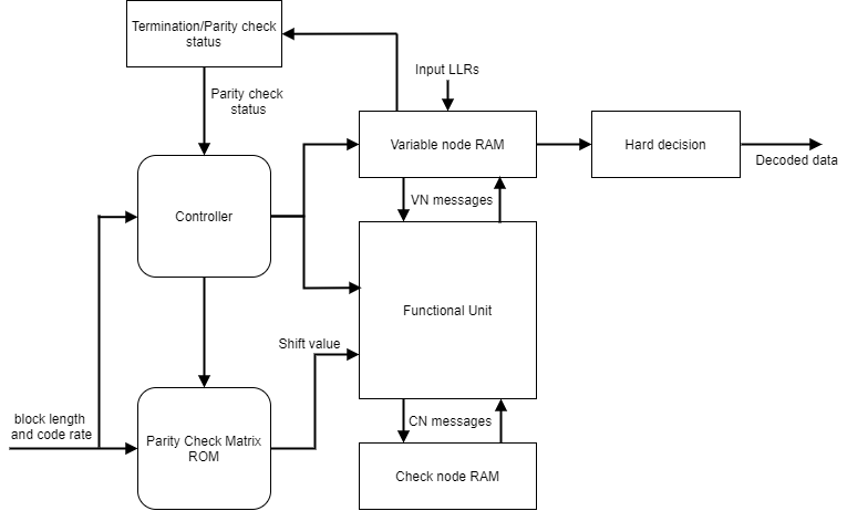
This figure shows the architecture block diagram of the WLAN LDPC Decoder block. The Controller block controls the layer and iteration count of the decoding process. The Variable node RAM block stores the variable node (VN) messages, and the Check node RAM block stores the check node (CN) messages. The Functional Unit block calculates the VN messages and CN messages based on the layered belief propagation and either the normalized min-sum approximation algorithm or the min-sum approximation algorithm. The Termination/Parity check status block calculates the parity checks and provides the parity check status after each iteration. For more information about decoding algorithms, see the following sections.

WLAN LDPC block architecture

References

[1] IEEE Std 802.11™-2016 (Revision of IEEE Std 802.11-2012). “Part 11: Wireless LAN Medium Access Control (MAC) and Physical Layer (PHY) Specifications.” IEEE Standard for Information technology — Telecommunications and information exchange between systems. Local and metropolitan area networks — Specific requirements.

[2] IEEE STD 802.11ad-2012 (Amendment to IEEE Std 802.11-2012, as amended by IEEE Std 802.11ae™-2012 and IEEE Std 802.11a™-2012). “Part 11: Wireless LAN Medium Access Control (MAC) and Physical Layer (PHY) Specifications. Amendment 4: Enhancements for Very High Throughput Operation in Bands below 6 GHz.” IEEE Standard for Information technology — Telecommunications and information exchange between systems. Local and metropolitan area networks — Specific requirements.

[3] IEEE Std 802.11ah™-2016 (Amendment to IEEE Std 802.11-2016 as amended by IEEE Std 802.11ai™-2016). “Part 11: Wireless LAN Medium Access Control (MAC) and Physical Layer (PHY) Specifications. Amendment 2: Sub 1 GHz License Exempt Operation.” IEEE Standard for Information technology — Telecommunications and information exchange between systems. Local and metropolitan area networks — Specific requirements.

[4] Gallager, R. “Low-Density Parity-Check Codes.” IEEE Transactions on Information Theory 8, no. 1 (January 1962): 21–28. https://doi.org/10.1109/TIT.1962.1057683.

[5] Hocevar, D.E. “A Reduced Complexity Decoder Architecture via Layered Decoding of LDPC Codes.” In IEEE Workshop OnSignal Processing Systems, 2004. SIPS 2004., 107–12. Austin, Texas, USA: IEEE, 2004. https://doi.org/10.1109/SIPS.2004.1363033.

[6] Chen, Jinghu, R.M. Tanner, C. Jones, and Yan Li. "Improved min-sum decoding algorithms for irregular LDPC codes." In Proceedings. International Symposium on Information Theory, 2005. ISIT 2005. https://doi: 10.1109/ISIT.2005.1523374.

Extended Capabilities

Version History

Introduced in R2021b