Arbitrarily Triggered CAN Message Transmission in Simulink
This example shows how to transmit CAN messages upon a generic condition.
The CAN Transmit block provides a feature to conditionally transmit CAN messages upon data change. When one of the input messages to the block changes, for example because one of the signal values changes, the block immediately transmits the message.
However, data change is not the only condition upon which a CAN message transmission can be triggered. In complex models, the triggering condition might be more generic. For example, a comparison of the value of a signal or a state variable to some set threshold.
Description
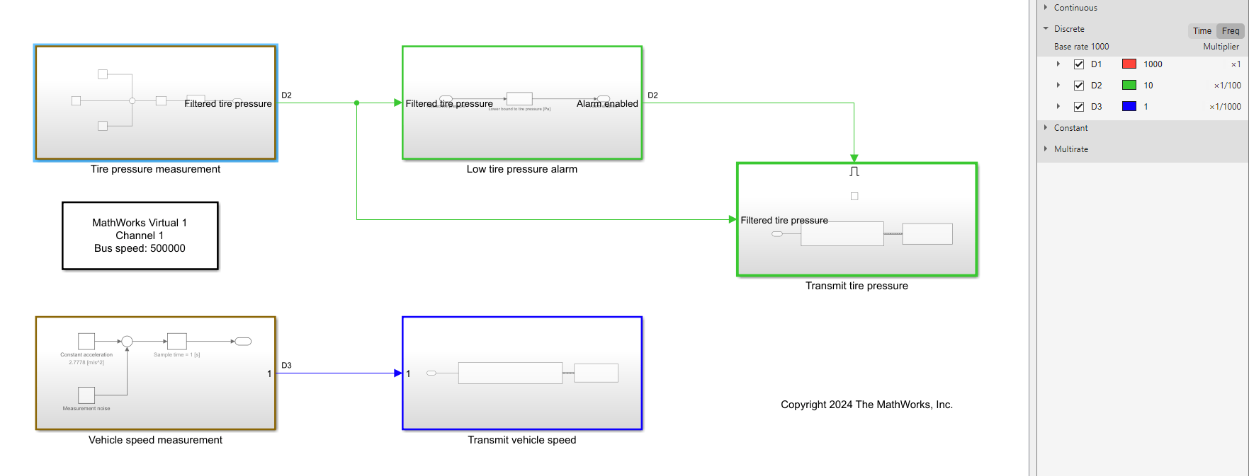
Consider the Simulink® model ArbitrarilyTriggeredCANTransmissionExample, which represents a simplified system to transmit values of the vehicle speed and the tire pressure over the CAN bus. A display system receives these values and makes them available to the driver. While vehicle speed needs to be continuously provided to the driver, tire pressure will be displayed only if its value is lower than a certain threshold, to indicate that the tire is deflated.
modelName = "ArbitrarilyTriggeredCANTransmissionExample";
open_system(modelName);
The model is organized as follows.
The "Tire pressure measurement" subsystem generates measurements of the tire pressure, and simulates a rapid pressure drop (from the nominal value of 3 bar or 300000 Pa) due to tire deflation. This subsystem contains a running average filter to smooth out the instantaneous pressure data to reduce the effect of measurement noise.
A downstream "Low tire pressure alarm" subsystem compares the filtered value of the pressure to a threshold and sets the alarm flag to true if the pressure becomes lower than this threshold.
The alarm flag activates the "Transmit tire pressure" subsystem, which contains a CAN Pack and a CAN Transmit block; this subsystem is conditionally transmitting the filtered pressure signal on the CAN bus.
The "Vehicle speed measurement" subsystem simulates a velocity signal corresponding to an acceleration from 0 to 100 km/h.
The "Transmit vehicle speed" subsystem includes the CAN Pack and CAN Transmit blocks, to transmit unconditionally the velocity signal on the bus.

The blocks in the "Transmit tire pressure" subsystem are configured as follows:
CAN Pack uses the external database file
CANBusArbitraryTrigger.dbcto encode and pack the signal.CAN Transmit is configured with the
On data changetransmit option enabled.
The model is configured using virtual channels, which allows receiving the transmitted messages in MATLAB®.
Note that, as shown by the sample time overlay in the model, the tire pressure signal and the vehicle speed signal are sampled at the different rates of 10 Hz and 1 Hz, respectively. The CAN Transmit block in the "Transmit vehicle speed" subsystem is configured to transmit on data change, so the transmission period will be 1 Hz. Similarly, the CAN Transmit block in the "Transmit tire pressure" subsystem is configured to transmit on data change, and the resulting transmission period will be 10 Hz; however, the signal will be transmitted only when the subsystem is activated.
Simulate Model and Log Data in MATLAB
Set up and start a canChannel in MATLAB to listen to the messages transmitted on MathWorks® virtual channel 1.
db = canDatabase("CANBusArbitraryTrigger.dbc");
canCh = canChannel("Mathworks", "Virtual 1", 2);
canCh.Database = db;
start(canCh);
Set up the simulation to use pacing, so that the model simulation time is approximately equal to wall-clock time. The execution of the script is paused accordingly.
StopTime = 10; % [s]
set_param(modelName, "EnablePacing", "on", "PacingRate", "1", "StopTime", num2str(StopTime));
set_param(modelName, "SimulationCommand", "start");
pause(StopTime);
Receive All Messages in the Buffer
msg = receive(canCh, inf, "OutputFormat", "timetable");
Post-Process the Messages
To display the Vehicle_Speed and Tire_Pressure signals, decode the received CAN messages in timetables.
Tmsg = canMessageTimetable(msg, db);
Tsig = canSignalTimetable(Tmsg);

plot(Tsig.Vehicle_Status.Time, Tsig.Vehicle_Status.Vehicle_Speed, "b*-");
yyaxis("left");
ylabel("Vehicle speed [m/s]");

hold("on");
plot(Tsig.Tire_Status.Time, Tsig.Tire_Status.Tire_Pressure/1e5, "rx-");
yyaxis("right");
ylabel("Tire pressure [bar]");
![Figure contains an axes object. The axes object with ylabel Tire pressure [bar] contains 2 objects of type line.](../../examples/vnt/win64/ArbitrarilyTriggeredCANMessageTransmissionInSimulinkExample_02.png)
In the figure above, notice the initial transmission delay due to the virtual channels, showing that the transmission effectively begins some time after the simulation starts. This is expected behavior when using virtual channels.
In addition, notice that the vehicle speed is monotonically increasing and sampled at 1 Hz. About 7 seconds from the beginning, the tire pressure drops below the threshold of 2.5 bar, and the transmission of the tire pressure signal begins. This signal is decreasing because the tire is deflating, and it is sampled at 10 Hz as expected.