Frame-Based Video Pipeline in Simulink
This example shows how to generate a sample-based IP core from a frame-based design in Simulink®.
This example uses the HDL Coder™ frame-to-sample optimization to generate an IP Core with AXI4-Stream interfaces from a frame-based MATLAB® design. The generated IP core can then be deployed to hardware and verified using live streaming data from MATLAB. This example explains the steps of importing an existing frame-based design from MATLAB into Simulink and then using HDL Workflow Advisor to generate HDL code and an FPGA bitstream.
In this example, you:
Model a frame-based video processing system as Design Under Test (DUT) and validate its functionality against a behavioral reference.
Configure the video processing system to generate HDL code using frame-to-sample workflow.
Generate an HDL IP core for the frame-based design with an AXI4-Stream interface.
Integrate the generated IP core into a reference design.
Use a simple script to run the design on hardware with live data.
Prerequisites
This example uses the HDL Coder Support Package for AMD FPGA and SoC Devices for bitstream generation. To run the example on hardware, you must run the guided hardware setup included in the support package installation.
On the MATLAB Home tab Toolstrip, in the Environment section, click Add-Ons > Manage Add-Ons.
Locate HDL Coder Support Package for AMD FPGA and SoC Devices, and click Setup.
The setup tool configures the target board and host machine, confirms that the target starts correctly, and verifies host-target communication. For more information, see Set Up AMD FPGA and SoC Devices (SoC Blockset).
Vivado® (To view the supported versions, see HDL Language Support and Supported Third-Party Tools and Hardware (HDL Coder))
SoC board. This example uses the Xilinx Zynq Ultrascale+ MPSoC ZCU102 Evaluation Kit.
Model Video Processing System as Design Under Test (DUT)
This section describes the design of the video processing system with preprocessing, edge detection, and postprocessing in a design-under-test (DUT) subsystem.
open_system('VideoProcessingSystem');


The figure shows the top level view of the VideoProcessingSystem.slx model. The InitFcn callback of the model configures the required workspace variables for the model using FBVP_SLSystemSetup script. The Select Frame subsystem selects the input frame from the inputFrames block. The input frame is then sent to FrameBasedVideoPipelineHDL for processing. The output is displayed using VideoViewer block.
open_system('VideoProcessingSystem/VideoPipelineDUT');

Frame-Based Video Pipeline in MATLAB
The example Frame-Based Video Pipeline shows a video processing pipeline for noise removal and edge detection. The pipeline has three main functions:
Preprocess: Resamples the input frame from 4:2:2 to 4:4:4 and converts YCbCr input to RGB.
Edge Detection and Overlay: Applies median filter for noise removal followed up by sharpening and bilateral filter for edge enhancement. The output of a bilateral filter is used for edge detection and is then processed using morphological closing. The edge-detected image is overlaid on the input frame.
Post processing: The obtained RGB image after overlay is converted back to YCbCr and the output format is updated to match with the input interface.
These algorithms are modeled in three referenced subsystems FrameBasedPreprocessing, FrameBasedEdgeDetection, and FrameBasedPostprocessing inside the referenced subsystem FrameBasedVideoPipelineHDL. The functions are taken from the MATLAB implementation in the Frame-Based Video Pipeline example.
Simulate and Validate Frame-Based Design
The input frames required to run the model are declared in FBVP_SLSystemSetup script. It is currently executed in the InitFcn callback. The DUT accepts concatenated YCbCr input. The pipeline simulation processes the frames and stores the result in the base workspace.
set_param("VideoProcessingSystem", SimulationCommand="update");
out = sim("VideoProcessingSystem");

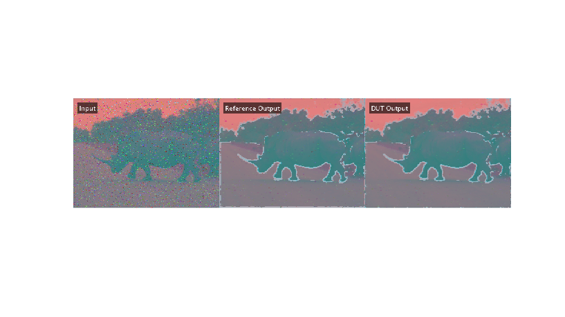
The FBVP_SLTestbench script validates processed frames from simulation against the reference. It calculates SSIM for the output frames obtained from simulation against the MATLAB reference and verifies that the SSIM exceeds the minimum threshold. The reference is calculated using FBVP_iptPipeline, that is shipped along with MATLAB example. The script displays the input frame, reference output, and DUT output.
run("FBVP_SLTestbench");
Configure Model for HDL Code Generation
Turn on Frame to Samples conversion for the input ports of the DUT in the HDL properties. Right-click the frameInChroma input port icon and select HDL Code > HDL Block Properties. On the Frame to Sample Conversion tab, set ConvertToSamples to on.

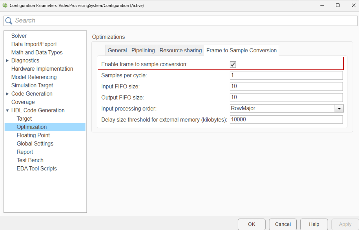
To enable the Frame to Sample optimization, set the FrameToSampleConversion properties to true in the model configuration parameters.
To generate HDL code, run makehdl with the name of the DUT subsystem.
makehdl("VideoProcessingSystem/VideoPipelineDUT");
You can either generate an FPGA bitstream by using the command line interface or by using HDL Workflow Advisor.
Generate IP Core using HDL Workflow Advisor
Start the targeting workflow by right clicking the VideoPipelineDUT subsystem and selecting HDL Code > HDL Workflow Advisor.
In step 1.1, select IP Core Generation workflow and the platform
Xilinx Zynq Ultrascale+ MPSoC ZCU102 Evaluation Kit.

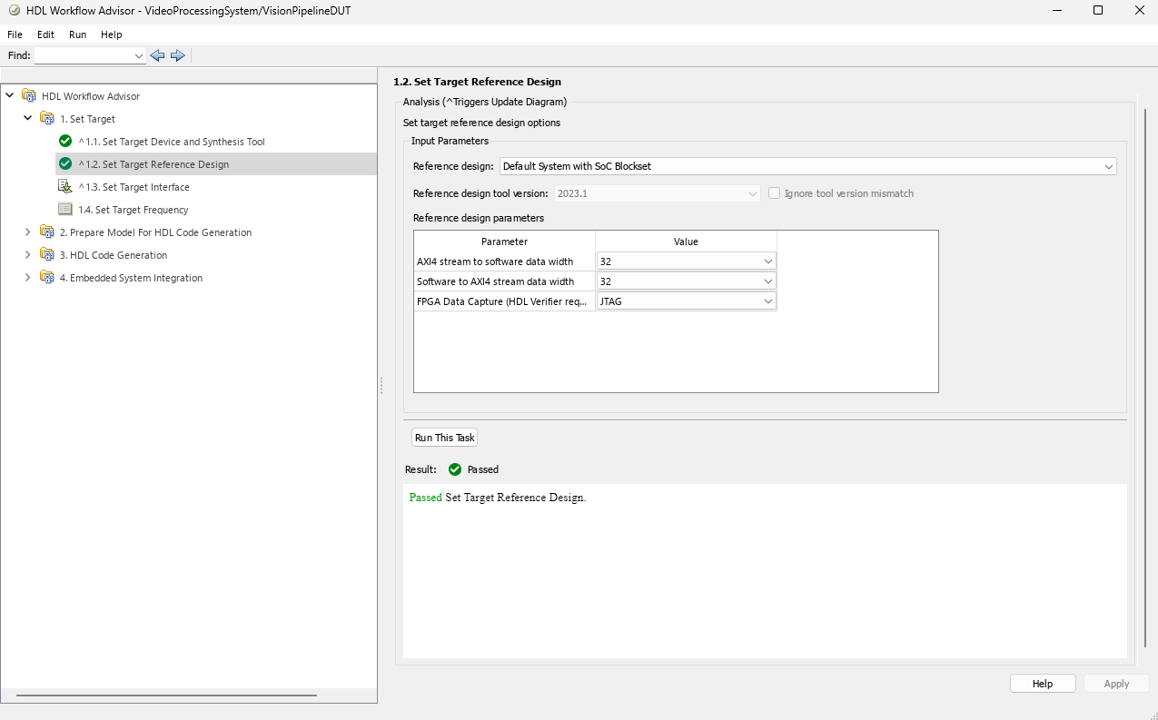
In step 1.2, set the reference design to
Default system with AXI4-Stream interface.
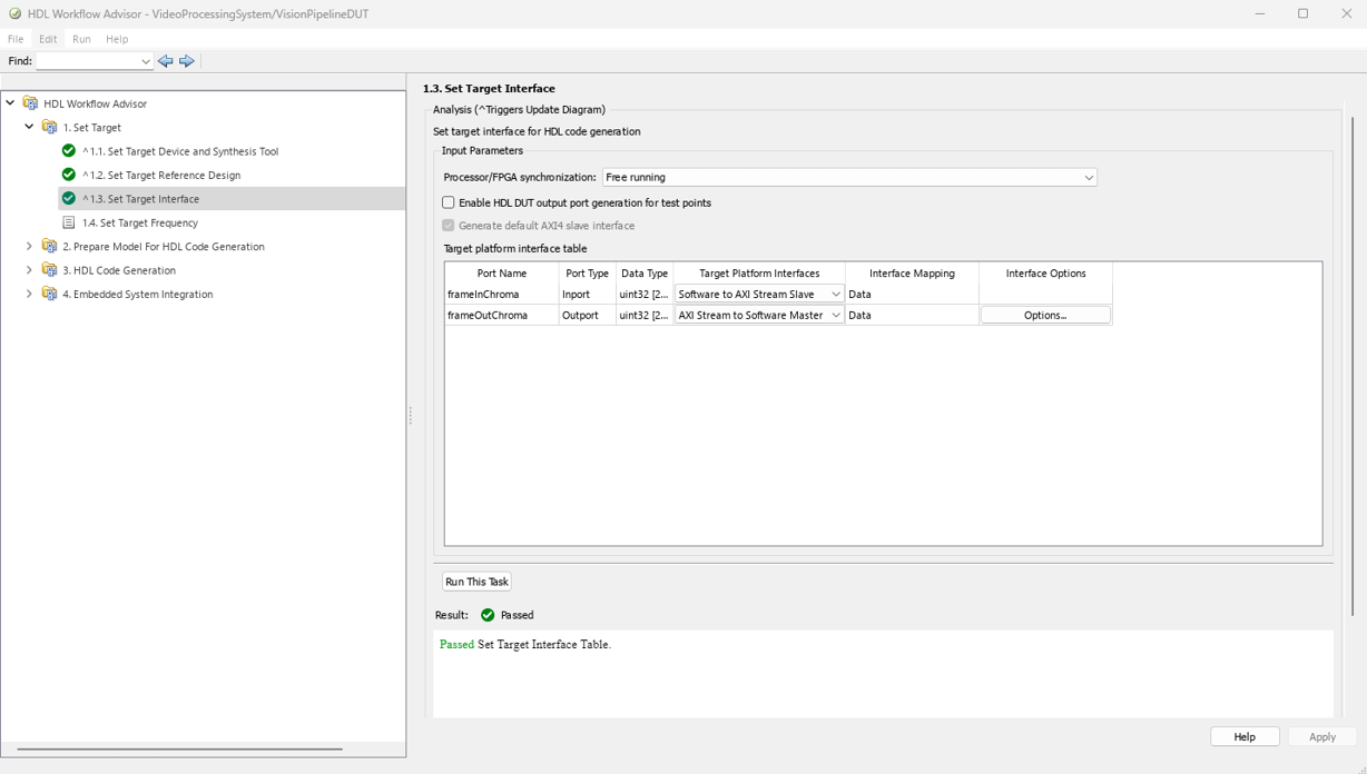
In step 1.3, map the target platform AXI stream interfaces to the input and output ports of the DUT.
In step 1.4, set the target frequency for the design to 150MHz.
Step 2 prepares the design for HDL code generation.
Step 3 generates HDL code for the IP core.
Step 4.1 integrates the newly generated IP core into the reference design.
In step 4.2, the host interface script and Zynq software interface model is created. Since this example uses the interface script, and not the model, uncheck Generate Simulink software interface model. The host interface script generated in this step,
gs_VideoProcessingSystem_setup, is used to set the target interfaces after programming the device.Step 4.3 generates the bitstream. The bit file is named
system_wrapper.bitand is located at hdl_prj\vivado_ip_prj\vivado_prj.runs\impl_1.Run Step 4.4 to build and download the FPGA bitstream.
Once the bitstream is generated, you can open HDL Code tab, select "Build Bitstream > Program Target Device" for deploying the bitstream for successive runs. Alternatively, you could also generate bitstream by directly clicking on "Build Bitstream" in HDL Code tab. This step generates the bitstream in an external shell.
Run Video Processing System on FPGA
You can interact with the FPGA design by reading and writing data from MATLAB on the host computer as described in the Interact with FPGA Design from Host Computer section of Prototype Generated IP Core on Hardware using FPGA I/O (HDL Coder). The host computer sends and receives frames of data from the board as shown in the high level architecture of the system:
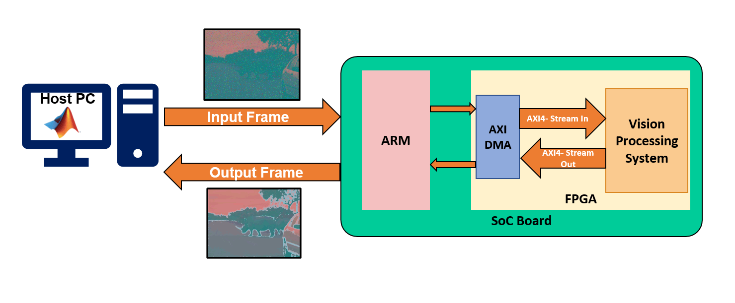
The script FBVP_HWTestbench sets the interfaces for the video processing system using gs_VideoProcessingSystem_setup function generated in WFA Step 4.3. Additionally, it generates input from rhinos.avi video and processes 10 frames using a video processing subsystem that resamples and enhances the input image. The output data read from hardware is rearranged from ufix24 to uint8 with Y,Cb,Cr channels.
Setup FPGA Connection Object
This function configures an object with the same interfaces as the generated IP core, and processes 10 frames of video.
hProcessor = xilinxsoc();
hFPGA      = fpga(hProcessor);
gs_VideoProcessingSystem_setup(hFPGA);
videoIn = VideoReader("rhinos.avi");
frameIn = videoIn.read(1);
frameHeight = size(frameIn,1);
frameWidth  = size(frameIn,2);
for ii=1:10
     % Add noise and blur, gamma for the input frame
     frameIn    = videoIn.read(ii);
     frameIn(:) = imfilter(frameIn, fspecial("gaussian", 3, 0.5)); % Gaussian blur
     frameIn(:) = imnoise(frameIn, "salt & pepper");               % Salt & pepper noise
% Input for Design Under Test (DUT)
frameInLinear = imadjust(frameIn, [], [], 2.2); % 2.2 to linear gamma
frameInChroma = rgb2ycbcr(frameInLinear); % Rearrange uint8 data to binary format to create ufix24 packed input
Y = uint8(dec2bin(frameInChroma(:,:,1)).'-'0')';
Cb = uint8(dec2bin(frameInChroma(:,:,2)).'-'0')';
Cr = uint8(dec2bin(frameInChroma(:,:,3)).'-'0')'; % Create packed ufix24 input frame.
packedIn = fi(bin2dec(char([Y Cb Cr]+'0')), 0, 24,0); % Write the frame to DUT using writePort
wrValid = writePort(hFPGA, "frameInChroma", frameInDUT); % Display the input frame
if wrValid
subplot(2,2,1), imagesc(frameInChroma);
title(sprintf('Input Frame %d',ii))
end % Read the output frame from DUT
[frameOutDUT, rd_valid] = readPort(hFPGA, "frameOutChroma"); % Rearrange the packed data into YCbCr channels.
YOut = uint8(bitsliceget(frameOutDUT, 24, 17));
CbOut = uint8(bitsliceget(frameOutDUT, 16, 9));
CrOut = uint8(bitsliceget(frameOutDUT, 8, 1)); % Reshape the data to the input size.
YOut = reshape(YOut, frameHeight, frameWidth);
CbOut = reshape(CbOut, frameHeight, frameWidth);
CrOut = reshape(CrOut, frameHeight, frameWidth);frameOutChroma = cat(3, YOut, CbOut, CrOut);
     if rdValid
         subplot(2,2,2), imagesc(frameOutChroma);
         title(sprintf('Processed Frame %d',ii))
     end
pause(0.5);
end
When you finish the example, run the last line of the script to release any hardware resources used by the fpga object:
release(hFPGA);