Getting Started with Frame-Based Image Filter
This example shows how to design a hardware-targeted image filter by using frame-based functions in MATLAB®.
Also, it shows:
Functional verification of the design
HDL code and testbench generation
HDL cosimulation
Modeling frame-based designs in Simulink®
Frame-Based Image Filter in MATLAB
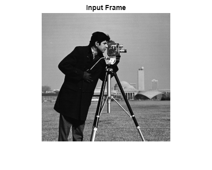
hdlimfilter is a frame-based image filter function which can be used for both simulation and HDL code generation. Import an input image, frameIn, and create filter coefficients to configure the filter function. The last two arguments of the filter function are padding method and padding value. In this case, the function pads the image with a constant value of zero. The function returns the filtered result in frameOut.
frameIn = im2single(imread('cameraman.tif'));
figure
imshow(frameIn,'InitialMagnification',100)
title 'Input Frame'

filter = [1 0; 0 -1];
frameOut = hdlimfilter(frameIn, filter,'Constant',0);
Simulation and Verification
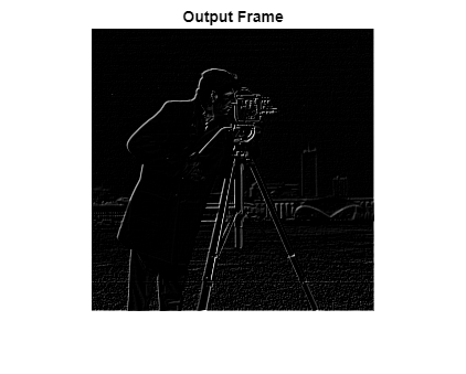
Once simulation is done, display the output frame. To verify the design, compare the output of the hdlimfilter function with the output of the Image Processing Toolbox™ imfilter function.
figure
imshow(frameOut,'InitialMagnification',100)
title 'Output Frame'

frameOutIPT = imfilter(frameIn,filter);

if(isequal(frameOutIPT,frameOut))
    disp('Passed')
else
    disp('Failed')
end
Passed
HDL Code Generation
To generate HDL code, first create an hdlcfg object, then set properties of the object.
Although the hdlimfilter function has frame-based input and output for simulation, the HDL code generation tools convert this interface to a streaming interface suitable for hardware. To enable this frame-to-sample conversion, set FrameToSampleConversion and AggressiveDataflowConversion properties to true. The AggressiveDataflowConversion property transforms the control flow algorithm of the code in the MATLAB function to a dataflow representation that is used for the frame-to-sample conversion optimization.
hdlcfg = coder.config('hdl');
DUT = 'hdlimfilter';
hdlcfg.DesignFunctionName = DUT;
hdlcfg.FrameToSampleConversion = true;
hdlcfg.AggressiveDataflowConversion = true;
Optionally, enable generation of an HDL test bench.
hdlcfg.GenerateHDLTestBench = true;
Provide the previous workspace variables as prototypes to communicate the size and type of the inputs to the function. This example uses floating-point input data, so enable native floating point support. Optionally, to enable multipixel processing, you can set SamplesPerCycle property to 2 or 4 or 8.
HDLframeIn = single(frameIn);
HDLfilter = single(filter);
hdlcfg.FloatingPointLibrary = 'NativeFloatingPoint';
hdlcfg.FloatingPointTargetConfiguration = hdlcoder.createFloatingPointTargetConfig();
% hdlcfg.SamplesPerCycle = 2;
To generate HDL code, run this command:
codegen -config hdlcfg -args { HDLframeIn coder.Constant(HDLfilter) coder.Constant('Constant') coder.Constant(1)}
### Begin MATLAB to HDL Code Generation...
### Working on DUT: hdlimfilter.
### The DUT requires an initial pipeline setup latency. Each output port experiences these additional delays.
### Output port 1: 44 cycles.
### Output port 1: The first valid output of this port will be after an initial latency of 257 valid inputs.
### Output port 2: 44 cycles.
### Output port 2: The first valid output of this port will be after an initial latency of 257 valid inputs.
### Output port 3: 44 cycles.
### MESSAGE: The design requires 65536 times faster clock with respect to the base rate = 1.
### Begin VHDL Code Generation
### Working on hdlimfilter/streaming_matrix_partition/frameIn_NeighborhoodCreator/counterNetwork as counterNetwork.vhd.
### Working on hdlimfilter/streaming_matrix_partition/frameIn_NeighborhoodCreator/NeighborhoodCreator_2x2/neighborhoodDelays as neighborhoodDelays.vhd.
### Working on hdlimfilter/streaming_matrix_partition/frameIn_NeighborhoodCreator/NeighborhoodCreator_2x2/lineBuffer/SimpleDualPortRAM_generic as SimpleDualPortRAM_generic.vhd.
### Working on hdlimfilter/streaming_matrix_partition/frameIn_NeighborhoodCreator/NeighborhoodCreator_2x2/lineBuffer as lineBuffer.vhd.
### Working on hdlimfilter/streaming_matrix_partition/frameIn_NeighborhoodCreator/NeighborhoodCreator_2x2 as NeighborhoodCreator_2x2.vhd.
### Working on hdlimfilter/streaming_matrix_partition/frameIn_NeighborhoodCreator/boundaryCounters_2_2 as boundaryCounters_2_2.vhd.
### Working on hdlimfilter/streaming_matrix_partition/frameIn_NeighborhoodCreator/BoundaryCheck_2x2 as BoundaryCheck_2x2.vhd.
### Working on hdlimfilter/streaming_matrix_partition/frameIn_NeighborhoodCreator as frameIn_NeighborhoodCreator.vhd.
### Working on hdlimfilter/FilterKernel/CoreImageFilter/nfp_add_single as nfp_add_single.vhd.
### Working on hdlimfilter/FilterKernel/CoreImageFilter/nfp_mul_single as nfp_mul_single.vhd.
### Working on hdlimfilter/FilterKernel/CoreImageFilter as CoreImageFilter.vhd.
### Working on hdlimfilter/Input_FIFOs/frameIn_FIFO/FIFO as FIFO.vhd.
### Working on hdlimfilter/Input_FIFOs/frameIn_FIFO as frameIn_FIFO.vhd.
### Working on hdlimfilter/Input_FIFOs as Input_FIFOs.vhd.
### Working on hdlimfilter/Output_FIFOs/frameOut_FIFO/FIFO as FIFO_block.vhd.
### Working on hdlimfilter/Output_FIFOs/frameOut_FIFO as frameOut_FIFO.vhd.
### Working on hdlimfilter/Output_FIFOs as Output_FIFOs.vhd.
### Working on hdlimfilter as hdlimfilter.vhd.
### Generating package file hdlimfilter_pkg.vhd.
### Generating Resource Utilization Report resource_report.html.
### Generating Optimization report
### To rerun codegen evaluate the following commands...

---------------------
cgi    = load('C:\ExampleManager\user.Bdoc.j2765272\visionhdl-ex17910972\codegen\hdlimfilter\hdlsrc\codegen_info.mat');
inVals = cgi.CodeGenInfo.inVals;
cfg    = cgi.CodeGenInfo.codegenSettings;
codegen -config cfg -args inVals -report
---------------------


### Begin TestBench generation.
### MATLAB testbench file not specified. Skipping HDL test bench generation.
### Generating HDL Conformance Report hdlimfilter_hdl_conformance_report.html.
### HDL Conformance check complete with 0 errors, 0 warnings, and 1 messages.
Code generation successful.
Verification with HDL Cosimulation
To manually simulate the generated DUT and testbench in QuestaSim®, follow either the GUI or programmatic steps.
To configure your HDL simulator environment variables, use the hdlsetuptoolpath function. For more details, see hdlsetuptoolpath (HDL Coder).
Simulate from QuestaSim GUI
Change directory to the location of your generated code, then open QuestaSim from MATLAB:
!vsim
In QuestaSim, compile the DUT and testbench by selecting these menu options:
Tools > Tcl > Execute Macro > DUT_tb_compile.do
Run the simulation:
Tools > Tcl > Execute Macro > DUT_tb_sim.do
Simulate from MATLAB Command Window
Change folder to the location of your generated code. To compile the DUT and testbench, call this command in MATLAB:
!vsim -do DUT_tb_compile.do -do DUT_tb_sim.do
Synthesis Settings
You can also use hdlcfg to simulate and synthesis the design automatically. For more details on coder.config properties, see coder.HdlConfig (HDL Coder).
This code shows how to configure the hdlcfg object to simulate in Modelsim™ and synthesize in Vivado® for a particular FPGA target.
% Simulation
hdlcfg.SimulateGeneratedCode = true;
hdlcfg.SimulationTool = 'ModelSim'; %  or 'ISIM'

% Enable Synthesis.
hdlcfg.SynthesizeGeneratedCode = true;

% Configure Synthesis tool.
hdlcfg.SynthesisTool = 'Xilinx Vivado'; %  or 'Altera Quartus II';
hdlcfg.SynthesisToolChipFamily = 'Zynq UltraScale+';
hdlcfg.SynthesisToolDeviceName = 'xczu9eg-ffvb1156-2-e';
hdlcfg.SynthesisToolPackageName = '';
hdlcfg.SynthesisToolSpeedValue = '';
hdlcfg.TargetFrequency = 300;

codegen -config hdlcfg -args { HDLframeIn coder.Constant(HDLfilter) coder.Constant('Constant') coder.Constant(1) }
For more information, see Generate HDL Code from MATLAB Code Using the Command Line Interface (HDL Coder).
Frame-Based Image Filter in Simulink
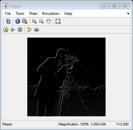
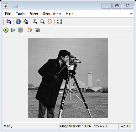
The ImageFilterDUT model shows how to use the hdlimfilter function with a MATLAB Function block in Simulink. The model also has an input data source and an output display. Simulate the model and observe the output. The output image matches that obtained from the MATLAB code earlier in this example.
close all;
open_system('ImageFilterDUT');
Warning: Method 'register' is not defined for class 'CloneDetectionUI.internal.CloneDetectionPerspective' or is removed from MATLAB's search path.
set_param("ImageFilterDUT", SimulationCommand="update");
out = sim("ImageFilterDUT");


Now, configure the model for HDL code generation and use makehdl(gcb) to generate HDL code and an HDL testbench. Right-click the MATLAB Function block, and select HDL Code > HDL Block Properties. Set the Architecture parameter to MATLAB Datapath.
To enable frame-to-sample conversion, set these properties:
hdlset_param("ImageFilterDUT", FrameToSampleConversion="on");
hdlset_param("ImageFilterDUT/DUT/In", ConvertToSamples="on"); % for each frame-based input port
hdlset_param("ImageFilterDUT", GenerateModel="on");
Now, you can use these commands to generate HDL code and an HDL testbench for the DUT subsystem.
%   makehdl("ImageFilterDUT/DUT")
%   makehdltb("ImageFilterDUT/DUT")
To deploy a frame-based design from Simulink® to an FPGA board, see Frame-Based Optical Flow Deployment with LK method.