Log Simulink Signals Using PX4 ULog
This example shows how to log signals in ULog format from a Simulink® model running on a Pixhawk® hardware and retrieve the log files from the SD card for further analysis.
This example uses a PX4® Pixhawk 6x as the hardware board. However, you can run this example using any PX4 Pixhawk hardware board.
Introduction
The UAV Toolbox Support Package for PX4 Autopilots supports logging of signals from your Simulink model on Pixhawk hardware in the ULog format. Signal logging enables you to monitor the behavior of the signal and perform analysis of historical data.
Prerequisites
If you are new to Simulink, watch the Simulink Quick Start video.
Perform the initial Setup and Configuration of the support package using Hardware Setup screens.
Required Hardware
To run this example, you will need the following hardware:
Pixhawk Series flight controller
Micro USB type-B cable
Micro-SD card (already used during the Performing PX4 System Startup from SD Card)
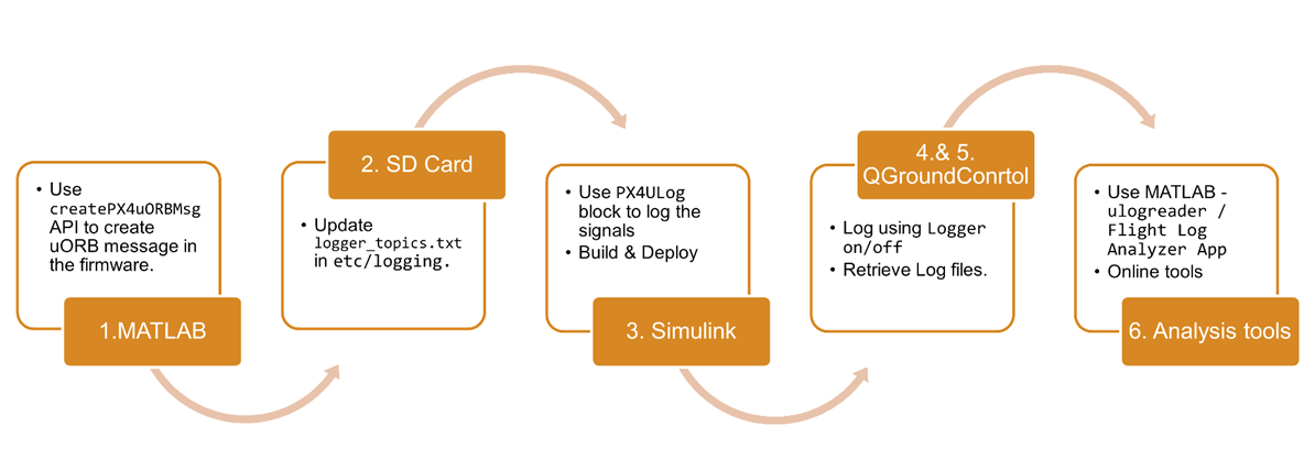
To log signals of your choice, follow the instructions provided below. The following image helps you in understanding the complete workflow.
Task 1: Getting Started with Logging Prebuild Custom uORB Message
In this task, you will utilize the pre-configured Simulink model to log few signals into the custom uORB message that builds during the Hardware Setup screens.
Step 1 - Include Custom uORB Message in Firmware
The first step requires you to create a new custom uORB message and include this in the firmware. To create a new message, use the createPX4uORBMessage MATLAB API. A custom message SimulinkCustomMessage is generated when performing the setup screens. This message is used in the current example to log signals.
This topic is configured to log 4 inputs with double and single data types. To log the desired signals, input the necessary information with appropriate data types for logging.
Step 2 - Update SD Card Configuration
You can customize the list of uORB topics to log by using a text file on the SD card. This needs to be updated with the new SL_CustomPX4uORBVerbose topic. Each time a new uORB message is created, this file includes the new topic to log. This step adheres with the current PX4 Logging workflow.
For more information, see PX4 Logging Workflow.
Note: There is a difference between the naming conventions used in MATLAB® and those used for PX4 logging. To use the generated uORB topic SimulinkCustomMessage you must change this before updating in the logger_topics.txt.
This step involves converting the names to lower case letters with a trailing underscore. Below is an example that illustrates this conversion process.

You can update the SD card configuration in one of two ways.
Use Terminal with Connected SD Card (Recommended method)
1. This method requires QGC to access the nsh console. In the QGC, navigate to Analyze Tools > MAVLink Console. If the console is not accessible, ensure to turn on the Enable MAVLink option as mentioned in Step 3, point 4.
2. Go to the etc/ folder on the SD Card and create a new logging folder. Use the following commands to create the folder, if it is not already created.
a. Access the location using the cd command.
nsh > cd fs/microsd/etc
b. Create the logging folder using the mkdir command.
nsh > mkdir logging
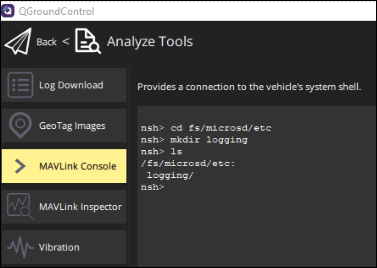
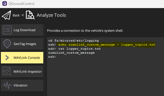
3. Once the logging folder is created, include a logger_topics.txt file is in this location.
Use the following command to include the text file logger_topics with the uORB topic
SimulinkCustomMessagementioned in the file.
nsh > echo simulink_custom_message >> logger_topics.txt
Manual Method - with SD Card disconnected
The above mentioned steps can be manually done by removing the SD card from Pixhawk board and accessing the contents.
Note: Along with the topic_name the instance and interval for the topic can be mentioned as additional information.
Example:

Step 3 - Open Model
1. Open the px4demo_ulog model.
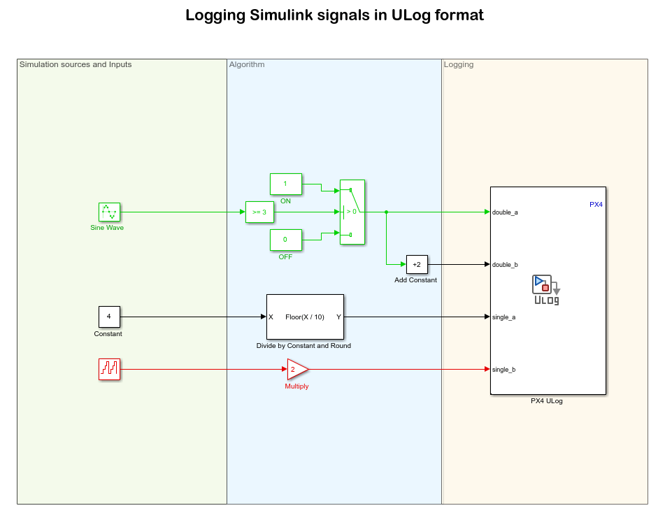
In the example model, the Simulink signals are connected to the PX4 ULog, which is responsible for logging the selected topic (SimulinkCustomMessage) on the block.
This block logs the input signals as a ULog file in the SD Card. The input signals are logged as a custom uORB topic as mentioned in the block parameters.
The name and number of inports are mentioned in the custom uORB topic.
This block internally maps the connected signals to the uORB Write block and is connected to a PX4 Timestamp block that writes the time from Hardware. Here the ports are updated as per message description for the selected topic SimulinkCustomMessage.
Note: In this example, sample time is set to 30ms, as there might be issues related to logging while using Pixracer board and sample time set to 10ms. However, there is no issue on other boards with sample time set to 10ms. For troubleshooting, see Dropouts and SD Cards.
The timestamp block PX4 Absolute Time in this model is required to write the timestamp from Pixhawk to Simulink. This timestamp information is useful to analyze the ULog data and can be used from the PX4 Utils library in the Simulink model. This Simulink model allows you to log the desired Simulink signals in a custom uORB topic, which can be analyzed later to gain insights. You can copy and paste this block to any other Simulink model using Ctrl + C and Ctrl + V keys on the keyboard.
2. Open the Model Configuration Parameters dialog box by selecting Modeling > Model Settings on the Simulink toolstrip.
3. Go to the Hardware Implementation pane and select the name of the target hardware from the Hardware board list. If you are using a hardware board other than the Pixhawk 6x, change the Hardware board selection.
4. In the Configuration Parameters dialog box, go to Hardware Implementation > Target hardware resources > MAVLink, and select Enable MAVLink on /dev/ttyACM0.
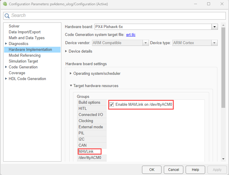
5. Click OK to close the dialog box.
Deploy the Simulink model to Pixhawk Hardware
In the Simulink model, on the Hardware tab, in the Mode section, select Run on board and then click Build, Deploy & Start. The build process for the model starts and it is deployed on the selected Hardware board.
Step 4 - Start PX4 Logger
The system logger in PX4 is responsible for logging information. Since this example is not a flying demo, you need to manually switch the logger on and off. By default, the PX4 logger is configured to log when the system is armed.
1. Access the PX4 console by opening QGC and selecting Analyze Tools > MAVLink Console for logging the topics.
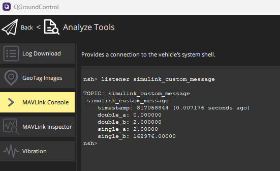
2. As an additional checkpoint before logging, ensure that the uORB message is being published by using listener topic_name command. For example, listener SimulinkCustomMessage.
3. In the PX4 console, use the logger on and logger off command to log the data. To verify the status of the logging process, use the logger status command.
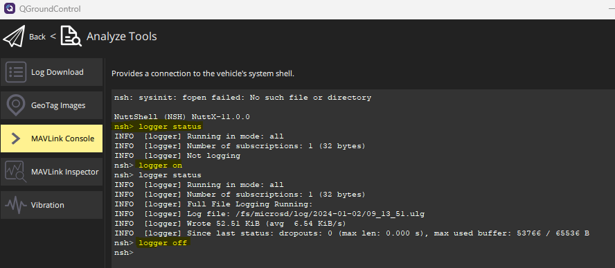
Note: If the logger is not started, use the logger start command to start it.
Step 5 - Retrieve the Data
Download the logged flight data to your system using the Log Download screen in QgroundControl (QGC).
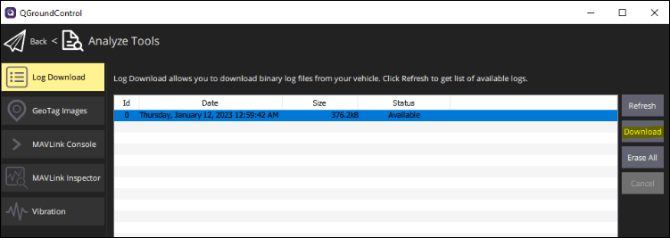
1. In the QGC, navigate to Analyze Tools > Log Download.
2. Click Refresh to get the latest logged flight data and then click Download to download the files.
Step 6 - Analyze ULog Data
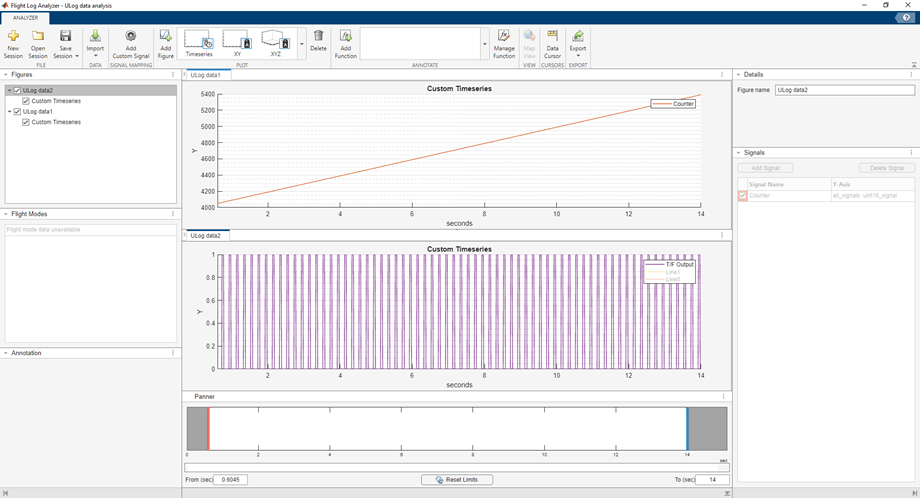
You can analyze the downloaded signals in MATLAB by using ulogreader, which enables you to import the data into workspace for further analysis. You can also use the Flight Log Analyzer to plot the data directly from ULog file as shown below.
For more online tools, see Flight Log Analysis.
Task 2: Create Custom uORB Message and Log in ULog Format
For an advanced workflow, you can create a message your choice as per the requirements and log them in uLog format. The uORB message can be created using the createPX4uORBMessage MATLAB API.
Assuming you have a Simulink model that requires a set of signals to be logged in uLog format, you can create the necessary custom message using the API, as illustrated below.
Use the following command in MATLAB terminal to create the custom uORB message.
>> createPX4uORBMessage ('NewExampleMessage','int16 int16_signal', 'int32 int32_signal', ...
'int64 int64_signal','uint8 uint8_signal','uint16 uint16_signal','uint32 uint32_signal', ...
'uint64 uint64_signal','float32 float32_signal','float64 float64_signal')
To use this custom uORB message, build the PX4 firmware using the Install UAV Toolbox Support Package for PX4 Autopilots in Linux.
A representation of the Simulink model for the generated new custom message is shown below.
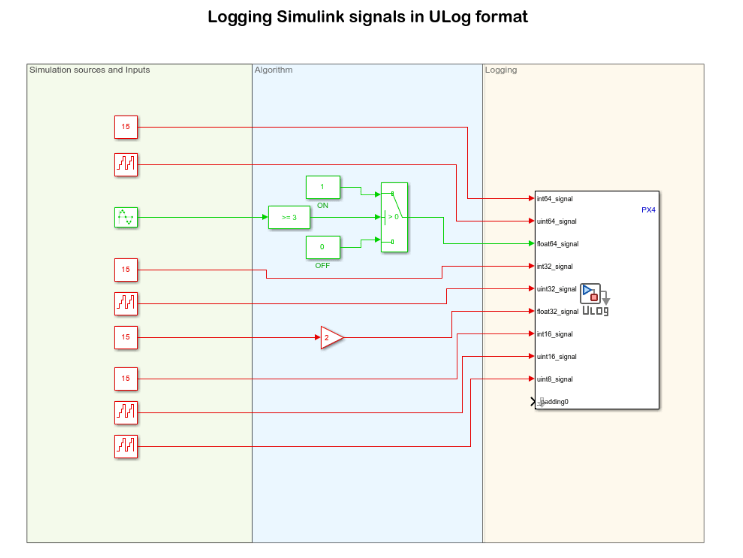
To log signals using ULog format from the illustrated Simulink model perform the steps listed from Step 2 to Step 6.
Note: In Step2, use the topic name new_example_message to update the logger_topics.txt.
nsh > echo new_example_message >> logger_topics.txt
Replace the example model (px4demo_ulog) in Step 3 with the your specified model. Next, proceed with points 2, 3, 4, and 5 to successfully log the desired signals in your model.
For more information on uORB messages, see PX4 User Guide.