Import Infineon XML Datasheets into Simscape Half-Bridge Block
This example shows how to import device parameters from Infineon® datasheets for IGBTs and diodes into a Half-Bridge (Ideal, Switching) block.
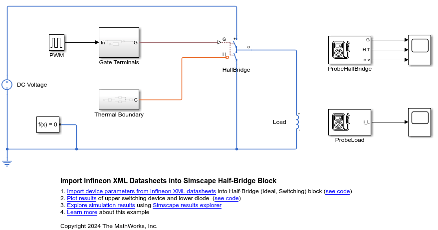
The Half-Bridge (Ideal, Switching) block uses ideal switching for fast simulation. You can optionally draw the requisite power due to switching losses from the electrical supply.
Model Overview
Open the model and specify the block path.
modelName = "ImportInfineonPartsIntoHalfBridge";
open_system(modelName);
blockPath = modelName + "/HalfBridge";

Import Device Parameters
Choose appropriate XML files to import device parameters into the Half-Bridge (Ideal, Switching) block.
switchingDeviceFile = "AIKQ200N75CP2_igbt.xml";
diodeFile = "AIKQ200N75CP2_diode.xml";
To import device parameters from Infineon datasheets, specify the switch-on and switch-off gate resistance values. The values must fall within the range the datasheets specify. You can open the datasheets to find minimum and maximum values.
gateResistanceOn = 9;
gateResistanceOff = 10;
Use the ee_importDeviceParameters function to import device parameters from the XML files into the block.
ee_importDeviceParameters({switchingDeviceFile,diodeFile},"infineon",blockPath,...
    GateResistanceOn=gateResistanceOn,GateResistanceOff=gateResistanceOff);
Observations
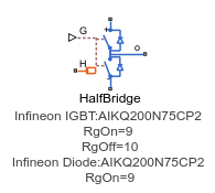
Observe the annotations under the Half-Bridge (Ideal, Switching) block after the parameterization.

If the datasheet does not provide a value, the function automatically assigns these parameters their default block parameter values and appends % Parameter not set to the value. Check for block parameters that contain % Parameter not set.
This table shows some of the block parameters.
Block Parameter | Parameter Value | Data Source |
Off-state conductance | 1e-06 % Parameter not set | Default value |
Temperature vector for losses, Tj | [25 100 150 175] | IGBT datasheet |
Junction temperatures, Tj | [25 175] | Diode datasheet |
offConductance = get_param(blockPath,"Goff");
temperatureVector = get_param(blockPath,"igbt_Tj_loss");
junctionTemperature = get_param(blockPath,"diode_TjVec");
Simulation Results
Simulate the model.
sim(modelName);
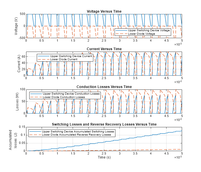
Plot the voltage, current, conduction losses, and switching losses for upper switching device and lower diode.
ImportInfineonPartsIntoHalfBridgePlot;

See Also
ee_importDeviceParameters | Half-Bridge (Ideal,
Switching)