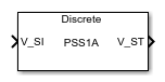
SM PSS1A
Discrete- or continuous-time single-input PSS1A power system stabilizer
Libraries:
Simscape /
Electrical /
Control /
SM Control
Description
The SM PSS1A block implements a single-input PSS1A power system stabilizer (PSS) that maintains rotor angle stability in a synchronous machine (SM) in conformance with IEEE 421.5-2016 [1]. Typically, you use a PSS to enhance the damping of power system oscillations through excitation control.
You can switch between continuous and discrete implementations of the block by using the
Sample time (-1 for inherited) parameter. To configure the
integrator for continuous time, set the Sample time (-1 for
inherited) property to 0. To configure the integrator
for discrete time, set the Sample time (-1 for inherited) property
to a positive, nonzero value, or to -1 to inherit the sample time
from an upstream block.
This diagram illustrates the overall structure of the PSS1A power system stabilizer:
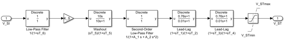
In the diagram:
V_SI is the power system stabilizer input. Commonly used inputs are speed, frequency, or power. For more information, see V_SI.
The Low-Pass Filter (Discrete or Continuous) block can be used to model a transducer, with a time constant T6.
Ks models the stabilizer gain.
The Washout (Discrete or Continuous) block models a high-pass filter. Here, T5 is the time constant.
The Second-Order Low-Pass Filter (Discrete or Continuous) block takes into account the low-frequency effects of the high-frequency torsional filters. Here, A1 and A2 are the stabilizer denominator constants for the second-order block.
The two Lead-Lag (Discrete or Continuous) blocks models additional dynamics associated with the power system stabilizer, and represent two stages of the lead-lag compensation.
Ports
Input
Output
Parameters
References
[1] “IEEE Recommended Practice for Excitation System Models for Power System Stability Studies.” IEEE Std 421.5-2016 (Revision of IEEE Std 421.5-2005), August 2016, 1–207. https://doi.org/10.1109/IEEESTD.2016.7553421.
[2] “IEEE Recommended Practice for Excitation System Models for Power System Stability Studies.” IEEE Std 421.5-2005 (Revision of IEEE Std 421.5-1992), April 2006, 1–93. https://doi.org/10.1109/IEEESTD.2006.99499.
[3] Kundur, P. Power System Stability and Control. New York, NY: McGraw Hill, 1993.
Extended Capabilities
Version History
Introduced in R2018b