Second-Order Filter
Discrete-time or continuous-time low-pass, high-pass, band-pass, or band-stop second-order filter
Libraries:
Simscape /
Electrical /
Control /
General Control
Description
The Second-Order Filter block implements different types of second-order filters. Filters are useful for attenuating noise in measurement signals.
The block provides these filter types:
Low pass — Allows signals, , only in the range of frequencies below the cutoff frequency, , to pass.
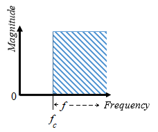
High pass — Allows signals, , only in the range of frequencies above the cutoff frequency, , to pass.
Band pass — Allows signals, , only in the range of frequencies between two cutoff frequencies, and , to pass.
Band stop — Prevents signals, , only in the range of frequencies between two cutoff frequencies, and , from passing.
| Filter Type | Frequency Range, | |
|---|---|---|
| Low-Pass |
| |
| High-Pass |
| |
| Band-Pass |
| |
| Band-Stop |
| |
Equations
The second order derivative state equation for the filter is:
Where:
x is the filter internal state.
u is the filter input.
ωn is the filter natural frequency.
ζ is the filter damping factor.
For each filter type, the table maps the block output, , as a function of the internal state of the filter, to the s-domain transfer function, .
| Filter Type | Output, | Transfer Function, |
|---|---|---|
| Low-Pass | ||
| High-Pass | ||
| Band-Pass | ||
| Band-Stop |
For Initialization:
Where:
is the initial state of the filter.
is the initial input to the filter.
is the AC component of the steady-state initial input.
is the initial amplitude.
is the initial phase.
is the DC component of the steady-state initial input.
is the initial bias.
In the s-domain . Therefore, for the initial frequency, :
Examples
Ports
Input
Output
Parameters
References
[1] Agarwal, A. and Lang, J. H. Foundations of Analog and Digital Electronic Circuits. New York: Elsevier, 2005.
Extended Capabilities
Version History
Introduced in R2018b


