Inductor
Inductor including optional tolerance, operational limits, and fault behavior

Libraries:
Simscape /
Electrical /
Passive
Description
The Inductor block lets you model linear inductors, including the following effects:
You can turn these modeling options on and off independently of each other. When all the additional options are turned off, the component behavior is identical to the Simscape™ Foundation library Inductor block.
In its simplest form, the Inductor block models a linear inductor, described with the following equation:
where:
V is voltage.
L is inductance.
I is current.
t is time.
To model a nonlinear inductor, use the Nonlinear Inductor block.
Tolerances
You can apply tolerances to the nominal value you provide for the Inductance parameter. Datasheets typically provide a tolerance percentage for a given inductor type. The table shows how the block applies tolerances and calculates inductance based on the selected Tolerance application option.
| Option | Inductance Value |
|---|---|
| L |
| Uniform distribution: L · (1
– tol + 2· tol· Gaussian
distribution: L · (1 + tol · |
| L · (1 + tol ) |
| L · (1 – tol ) |
In the table,
L is the Inductance parameter value, nominal inductance.
tol is fractional tolerance, Inductance tolerance (%) /100.
nSigma is the value you provide for the Number of standard deviations for quoted tolerance parameter.
randandrandnare standard MATLAB® functions for generating uniform and normal distribution random numbers.
Note
If you choose the Random tolerance option and you are in
"Fast Restart" mode, the random tolerance value is updated on every simulation if at least
one between the fractional tolerance, tol, or the Number of
standard deviations for quoted tolerance, nSigma, is set
to Run-time and is defined with a variable (even if you do not modify that
variable).
Operating Limits
Inductors are typically rated with a particular saturation current, and possibly with a maximum allowable power dissipation. You can specify operating limits in terms of these values, to generate warnings or errors if the inductor is driven outside its specification.
When an operating limit is exceeded, the block can either generate a warning or stop the simulation with an error. For more information, see the Operating Limits parameters section.
Faults
To model a fault in the Inductor block, in the Faults section, click Add fault next to the fault that you want to model. For more information about fault modeling, see Fault Behavior Modeling and Fault Triggering.
Instantaneous changes in inductor parameters are unphysical. Therefore, when the Inductor block enters the faulted state, short-circuit and open-circuit voltages transition to their faulted values over a period of time based on this formula:
CurrentValue = FaultedValue –
(FaultedValue – UnfaultedValue)
· sech(∆t / τ)
where:
∆t is time since the onset of the fault condition.
τ is user-defined time constant associated with the fault transition.
For short-circuit faults, the conductance of the short-circuit
path also changes according to the sech(∆t
/ τ) function from a small value (representing an open-circuit
path) to a large value.
The block can trigger the start of fault transition:
At a specific time.
After the voltage exceeds the maximum permissible value a certain number of times.
When the current exceeds the maximum permissible value for longer than a specific time interval.
If you want to trigger a fault at a specific time, in the
Fault Inspector window, set Trigger type to
Timed. If you want to determine whether a system fails and, if
so, when it fails, in the Fault Inspector window, set Trigger
type to Behavioral.
If you select the behavioral trigger, the component fails as soon as one of the trigger conditions is true.
Faultable inductors often require that you use the fixed-step local solver, especially if your model transitions to a faulted state that includes short circuits. For more information, see Making Optimal Solver Choices for Physical Simulation.
Variables
To set the priority and initial target values for the block variables before simulation, use the Initial Targets section in the block dialog box or Property Inspector. For more information, see Set Priority and Initial Target for Block Variables.
Use nominal values to specify the expected magnitude of a variable in a model. Using system scaling based on nominal values increases the simulation robustness. Nominal values can come from different sources. One of these sources is the Nominal Values section in the block dialog box or Property Inspector. For more information, see System Scaling by Nominal Values.
The Inductor current variable lets you specify a high-priority target for the initial inductor current at the start of simulation.
Examples

Buck Converter with Faults
Model and assess the impact of component tolerances and fault events on the operation of a switching power supply. The R, L, and C components all have tolerances, operational limits, and faults defined. The faults can be enabled within the block dialog or using MATLAB® Commands. The capacitor fault is already enabled to cut in at 1.5e-3 seconds.
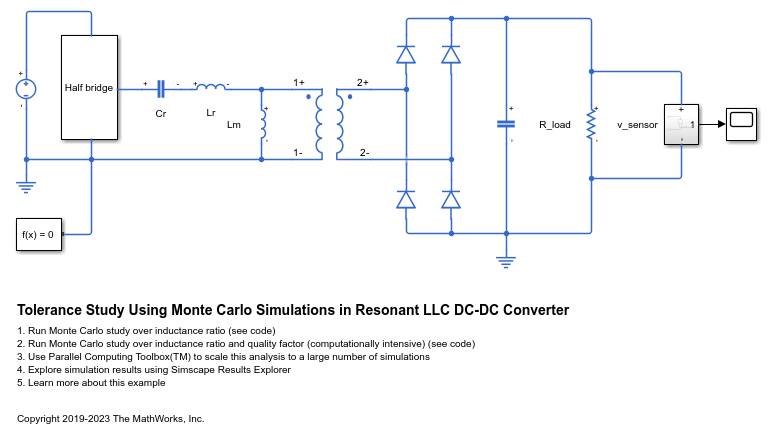
Tolerance Study Using Monte Carlo Simulations in Resonant LLC DC-DC Converter
Use Simscape™ Electrical™ to perform a Monte Carlo analysis to optimize the design of an LLC resonant DC-DC converter when some of its components have tolerances.