Main Content

Permanent Magnet Synchronous Machine

Three-phase permanent magnet synchronous machine with sinusoidal or trapezoidal back electromotive force, or five-phase permanent magnet synchronous machine with sinusoidal back electromotive force

  • Permanent Magnet Synchronous Machine block

Libraries:
Simscape / Electrical / Specialized Power Systems / Electrical Machines

Description

The Permanent Magnet Synchronous Machine block implements a three-phase or a five-phase permanent magnet synchronous machine. The stator windings are connected in wye to an internal neutral point.

The three-phase machine can have a sinusoidal or trapezoidal back EMF waveform. The rotor can be round or salient-pole for the sinusoidal machine. The rotor is round when the machine is trapezoidal. Preset models are available for the sinusoidal back EMF machine.

The five-phase machine has a sinusoidal back EMF waveform and round rotor.

The Permanent Magnet Synchronous Machine block operates in either generator or motor mode. The mode of operation is dictated by the sign of the mechanical torque (positive for motor mode, negative for generator mode). The electrical and mechanical parts of the machine are each represented by a second-order state-space model.

The sinusoidal model assumes that the flux established by the permanent magnets in the stator is sinusoidal, which implies that the electromotive forces are sinusoidal.

The trapezoidal model assumes that the winding distribution and flux established by the permanent magnets produce three trapezoidal back EMF waveforms.

Three-Phase Sinusoidal Model Electrical System

These equations are expressed in the rotor reference frame (qd frame). All quantities in the rotor reference frame are referred to the stator.

ddtid=1LdvdRLdid+LqLdpωmiq

ddtiq=1LqvqRLqiqLdLqpωmidλpωmLq

Te=1.5p[λiq+(LdLq)idiq]

Lq, Ld

q-axis and d-axis inductances

R

Resistance of the stator windings

iq, id

q-axis and d-axis currents

vq, vd

q-axis and d-axis voltages

ωm

Angular velocity of the rotor

λ

Amplitude of the flux induced by the permanent magnets of the rotor in the stator phases

p

Number of pole pairs

Te

Electromagnetic torque

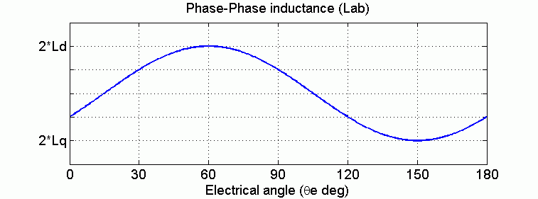
The Lq and Ld inductances represent the relation between the phase inductance and the rotor position due to the saliency of the rotor. For example, the inductance measured between phase A and B (when phase C is left open) is given by:

Lab=Ld+Lq+(LqLd)cos(2θe+π3),

where Θe represents the electrical angle.

The next figure shows the variation of the phase-to-phase inductance in function of the electrical angle of the rotor.
  • For a round rotor, there is no variation in the phase inductance:

    Ld=Lq=Lab2.

  • For a salient round rotor, the dq inductances are given by:

    Ld=max(Lab)2

    Lq=min(Lab)2

Five-Phase Sinusoidal Model Electrical System

These equations are expressed in the rotor reference frame using an extended Park transformation (q1d1 and q2d2 frame). All quantities in the rotor reference frame are referred to the stator.

ddtid1=1Lvd1RLid1+LqLpωmiq1

ddtiq1=1Lvq1RLiq1LdLpωmid1λpωmL

ddtid2=1Lvd2RLid2

ddtiq2=1Lvq2RLiq2

Te=2.5pλiq1

L

Armature inductance

R

Resistance of the stator windings

iq1, id1

q1-axis and d1-axis currents

vq1, vd1

q1-axis and d1-axis voltages

iq2, id2

q2-axis and d2-axis currents

vq2, vd2

q2-axis and d2-axis voltages

ωm

Angular velocity of the rotor

λ

Amplitude of the flux induced by the permanent magnets of the rotor in the stator phases

p

Number of pole pairs

Te

Electromagnetic torque

Three-Phase Trapezoidal Model Electrical System

These equations are expressed in the phase reference frame (abc frame). Note that the phase inductance Ls is assumed to be constant and does not vary with the rotor position.

ddtia=13Ls(2vab+vbc3Rsia+λpωm(2Φa+Φb+Φc))ddtib=13Ls(vab+vbc3Rsib+λpωm(Φa2Φb+Φc))ddtic=(ddtia+ddtib)Te=pλ(Φaia+Φbib+Φcic)

Ls

Inductance of the stator windings

R

Resistance of the stator windings

ia, ib, ic

a, b and c phase currents

Φa', Φb', Φc'

a, b and c phase electromotive forces, in per-unit value to the amplitude of the flux λ

vab, vbc

ab and bc phase to phase voltages

ωm

Angular velocity of the rotor

λ

Amplitude of the flux induced by the permanent magnets of the rotor in the stator phases

p

Number of pole pairs

Te

Electromagnetic torque

The electromotive force Φ' is represented by:

Mechanical System

ddtωm=1J(TeTfFωmTm)dθdt=ωm

J

Combined inertia of rotor and load

F

Combined viscous friction of rotor and load

θ

Rotor angular position

Tm

Shaft mechanical torque

Tf

Shaft static friction torque

ωm

Angular velocity of the rotor (mechanical speed)

Examples

Limitations and Assumptions

When you use Permanent Magnet Synchronous Machine blocks in discrete systems, you might have to use a small parasitic resistive load, connected at the machine terminals, to avoid numerical oscillations. Large sample times require larger loads. The minimum resistive load is proportional to the sample time. Remember that with a 25 μs time step on a 60 Hz system, the minimum load is approximately 2.5% of the machine nominal power. For example, a 200 MVA permanent magnet synchronous machine in a power system discretized with a 50 μs sample time requires approximately 5% of resistive load, or 10 MW. If the sample time is reduced to 20 μs, a resistive load of 4 MW is sufficient.

The Permanent Magnet Synchronous Machine block assumes a linear magnetic circuit with no saturation of the stator and rotor iron. This assumption can be made because of the large air gap usually found in permanent magnet synchronous machines.

Ports

Input

expand all

Mechanical torque at the machine shaft. This input port is normally positive because the Permanent Magnet Synchronous Machine block is usually used as a motor. If you choose to use the block in generator mode, you can apply a negative torque input.

Dependencies

To enable this port, set Mechanical input to Torque Tm.

Machine speed, in rad/s.

Dependencies

To enable this port, set Mechanical input to Speed w.

Output

expand all

Vector containing measurement signals. The block returns a 13-element vector when Number of phases is set to 3, and a 16-element vector when Number of phases is set to 5. The available signals depend on the model you selected. You can demultiplex these signals by using the Bus Selector block provided in the Simulink® library. The signals include:

Name

Definition

Units

Model

ias

Stator current is_a

A

All

ibs

Stator current is_b

A

All

ics

Stator current is_c

A

All

ids

Stator current is_d

A

Five-Phase Sinusoidal

ies

Stator current is_e

A

Five-Phase Sinusoidal

iqs

Stator current is_q

A

Three-Phase Sinusoidal

ids

Stator current is_d

A

Three-Phase Sinusoidal

iqs1

Stator current is_q1

A

Five-Phase Sinusoidal

ids1

Stator current is_d1

A

Five-Phase Sinusoidal

iqs2

Stator current is_q2

A

Five-Phase Sinusoidal

ids2

Stator current is_d2

A

Five-Phase Sinusoidal

vqs

Stator voltage Vs_q

V

Three-Phase Sinusoidal

vds

Stator voltage Vs_d

V

Three-Phase Sinusoidal

vqs1

Stator voltage Vs_q1

V

Five-Phase Sinusoidal

vds1

Stator voltage Vs_d1

V

Five-Phase Sinusoidal

vqs2

Stator voltage Vs_q2

V

Five-Phase Sinusoidal

vds2

Stator voltage Vs_d2

V

Five-Phase Sinusoidal

ea

Phase back EMF e_a

V

Three-Phase Trapezoidal

eb

Phase back EMF e_b

V

Three-Phase Trapezoidal

ec

Phase back EMF e_c

V

Three-Phase Trapezoidal

ha

Hall effect signal h_a*

logical (0 or 1)

Three-Phase, Sinusoidal and Trapezoidal

hb

Hall effect signal h_b*

logical (0 or 1)

Three-Phase, Sinusoidal and Trapezoidal

hc

Hall effect signal h_c*

logical (0 or 1)

Three-Phase, Sinusoidal and Trapezoidal

w

Rotor speed wm

rad/s

All

theta

Rotor angle thetam

rad

All

Te

Electromagnetic torque Te

N.m

All

The Hall effect signal provides a logical indication of the back EMF positioning. This signal is very useful to directly control the power switches. There is a change of state at each zero crossing of the phase-to-phase voltage. These signals must be decoded before being applied to the switches.

Conserving

expand all

Mechanical rotational port, that represents the rotational shaft of the machine.

Dependencies

To enable this port, set Mechanical input to Mechanical rotational port.

Specialized electrical conserving port associated with the electrical terminal of phase A.

Specialized electrical conserving port associated with the electrical terminal of phase B.

Specialized electrical conserving port associated with the electrical terminal of phase C.

Parameters

expand all

Configuration

Select between a three-phase machine model or a five-phase machine model.

Select between Sinusoidal and Trapezoidal electromotive force.

Dependencies

To enable this parameter, set Number of phases to 3.

Select between Salient-pole and Round rotors.

Dependencies

To enable this parameter, set Number of phases to 3 and set Back EMF waveform to Sinusoidal.

Select whether input is supplied by torque applied to the shaft, rotor speed, or a machine shaft represented by a Simscape™ rotational mechanical port.

Select Torque Tm to specify a torque input in N.m and expose the Tm port. The machine speed is determined by the machine Inertia J and by the difference between the applied mechanical torque Tm and the internal electromagnetic torque Te. The sign convention for the mechanical torque is when the speed is positive. A positive torque signal indicates motor mode and a negative signal indicates generator mode.

Select Speed w to specify a speed input in rad/s and expose the w port. The machine speed is imposed and the mechanical part of the model (Inertia J) is ignored. Using the speed as the mechanical input allows modeling a mechanical coupling between two machines.

The next figure indicates how to model a stiff shaft interconnection in a motor-generator set when friction torque is ignored in machine 2. The speed output of machine 1 (the motor) is connected to the speed input of machine 2 (the generator), while the machine 2 electromagnetic torque output, Te, is applied to the mechanical torque input of machine 1, Tm. The Kw factor takes into account the speed units of both machines (pu or rad/s) and the gear box ratio w2/w1. The KT factor takes into account the torque units of both machines (pu or N.m) and machine ratings. Also, because the inertia J2 is ignored in machine 2, J2 is added to the machine 1 inertia, J1.

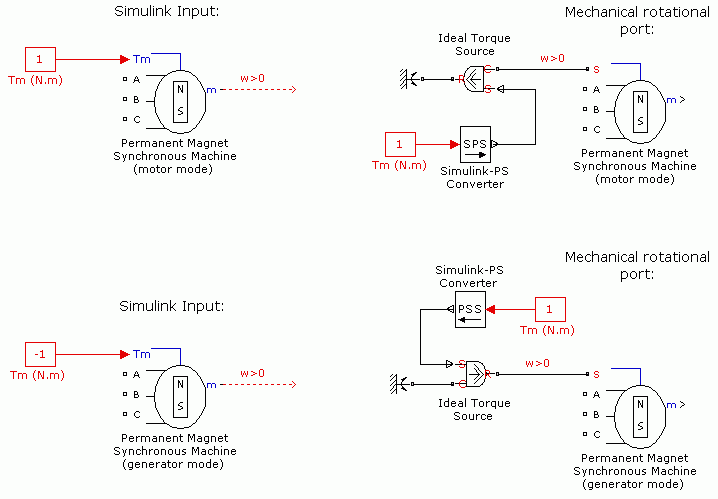
Select Mechanical rotational port to expose a Simscape mechanical rotational port that allows you to connect the machine shaft to other Simscape blocks with mechanical rotational ports.

The next figure indicates how to connect an Ideal Torque Source block from the Simscape library to the machine shaft to represent the machine in motor mode or in generator mode.

Predetermined electrical and mechanical parameters for various permanent magnet synchronous motor ratings of torque (N.m), DC bus voltage (V), rated speed (rpm), and continuous stall torque (N.m).

Select one of the preset models to load the corresponding electrical and mechanical parameters in the entries of the dialog box. Select No (default) if you do not want to use a preset model, or if you want to modify some of the parameters of a preset model.

The available preset models are:

  • No

  • 01: 0.8 Nm 300 Vdc 3000 RPM - 0.8 Nm

  • 02: 1.7 Nm 300 Vdc 3750 RPM - 1.7 Nm

  • 03: 2.8 Nm 300 Vdc 4250 RPM - 3.2 Nm

  • 04: 6 Nm 300 Vdc 4500 RPM - 6 Nm

  • 05: 8 Nm 300 Vdc 2000 RPM - 10 Nm

  • 06: 10 Nm 300 Vdc 2300 RPM - 14.2 Nm

  • 07: 20 Nm 300 Vdc 2200 RPM - 33.9 Nm

  • 08: 24 Nm 300 Vdc 2300 RPM - 41.4 Nm

  • 09: 7.14 Nm 560 Vdc 5000 RPM - 8.3 Nm

  • 10: 7.71 Nm 560 Vdc 5000 RPM - 10.2 Nm

  • 11: 26.13 Nm 560 Vdc 3000 RPM - 27.3 Nm

  • 12: 35.17 Nm 560 Vdc 3000 RPM - 37.4 Nm

  • 13: 42.09 Nm 560 Vdc 3000 RPM - 45.6 Nm

  • 14: 67.27 Nm 560 Vdc 1700 RPM - 70.2 Nm

  • 15: 87.75 Nm 560 Vdc 3000 RPM - 97.96 Nm

  • 16: 111 Nm 560 Vdc 3000 RPM - 126 Nm

When you select a preset model, the electrical and mechanical parameters in the Parameters tab of the dialog box are disabled. To start from a given preset model and then modify machine parameters:

  1. Select the preset model for which you want to initialize the parameters.

  2. Change Preset model to No. This does not change the machine parameters in the Parameters tab.

  3. Modify the machine parameters, then click Apply.

Dependencies

To enable this parameter, set Number of phases to 5, or set Number of phases to 3 and Back EMF waveform to Sinusoidal.

When selected, the measurement output uses the signal names to identify the bus labels. Select this option for applications that require bus signal labels to have only alphanumeric characters.

When cleared, the measurement output uses the signal definition to identify the bus labels. The labels contain nonalphanumeric characters that are incompatible with some Simulink applications.

Parameters

Stator phase resistance Rs (Ω).

Stator-phase-to-neutral inductance Ls (H) of the trapezoidal model.

Dependencies

To enable this parameter, set Number of phases to 3 and Back EMF waveform to Trapezoidal.

Phase-to-neutral Ld (H) and Lq (H) inductances in the d-axis and q-axis of the sinusoidal model with a salient-pole rotor.

Dependencies

To enable this parameter, set Number of phases to 3, Back EMF waveform to Sinusoidal, and Rotor type to Salient-pole.

Armature inductance of the sinusoidal model with a round rotor. Ld is equal to Lq.

Dependencies

To enable this parameter, set Number of phases to 3, Back EMF waveform to Sinusoidal, and Rotor type to Round.

Machine constant for block parameterization. Once you select a constant, you can enter its value in the appropriate parameter field, while the other two parameters are disabled.

Constant flux λ (Wb) per pole pairs induced in the stator windings by the magnets.

Dependencies

To enable this parameter, set Specify to Flux linkage established by magnets (V.s).

Peak line-to-line voltage per 1000 rpm. This voltage represents the peak open circuit voltage when the machine is driven as a generator at 1000 rpm.

Dependencies

To enable this parameter, set Specify to Voltage Constant (V_peak L-L / krpm).

Torque per ampere constant. This constant assumes that the machine is driven by an inverter that provides a perfect synchronization between the current and the back EMF.

  • Sinusoidal model: A sine wave current is assumed.

  • Trapezoidal model: A square ware current is assumed.

Dependencies

To enable this parameter, set Specify to Torque Constant (N.m / A_peak).

Width of the flat top for a half period of the electromotive force Φ' (degrees) for a trapezoidal machine.

Dependencies

To enable this parameter, set Number of phases to 3 and Back EMF waveform to Trapezoidal.

Combined machine and load inertia coefficient J (kg.m2), combined viscous friction coefficient F (N.m.s), pole pairs p, and shaft static friction Tf (N.m). If the fourth value of the vector (static friction) is not specified, the block considers this value to be 0.

Dependencies

To enable this parameter, set Mechanical input to Torque Tm or Mechanical rotational port.

Number of pole pairs, p.

Dependencies

To enable this parameter, set Mechanical input to Speed w.

Mechanical speed (rad/s), mechanical angle Θm (degrees), and instantaneous stator current (A) for a three-phase machine [wm, Θm, ia, ib].

Because the stator is wye-connected and the neutral point is isolated, the current ic in the three-phase machine is given by ic = -ia-ib.

Dependencies

To enable this parameter, set Number of phases to 3.

Mechanical speed (rad/s), mechanical angle Θm (degrees), and instantaneous stator current (A) for a five-phase machine [wm, Θm, ia, ib, ic, id].

Because the stator is wye-connected and the neutral point is isolated, the current ie in the five-phase machine is given by ie = -ia -ib -ic -id.

Dependencies

To enable this parameter, set Number of phases to 5.

Reference position of the rotor flux relative to the phase A axis.

Select 90 degrees behind phase A axis (modified Park) to choose the reference position of the rotor represented by:

The modified Park transformation [4] is more convenient for vector control because the maximum phase induction occurs at theta = 0.

Select Aligned with phase A axis (original Park) to choose the reference position of the rotor represented by:

Advanced

To enable the Advanced tab, set the Simulation type parameter of the powergui block to Discrete and, on the Preferences tab, clear the Automatically handle discrete solver and Advanced tab solver settings of blocks parameter.

Integration method used by the block.

When you select the Automatically handle discrete solver and Advanced tab solver settings of blocks parameter in the powergui block, the discrete solver model is automatically set to Trapezoidal robust.

Trapezoidal non iterative requires you to add a non-negligible shunt load at the machine terminals to maintain simulation stability, and the simulation may fail to converge and stop when the number of machines increases in the model.

Trapezoidal robust and Backward Euler robust allow you to eliminate the need to use parasitic loads. To eliminate the topological errors of the machines connected to an inductive circuit (for example, a circuit breaker connected in series with the machine), the machine models a negligible internal load of 0.01% of nominal power.

Trapezoidal robust is slightly more accurate than Backward Euler robust, especially when the model is simulated at larger sample times. Trapezoidal robust may produce slight damped numerical oscillations on machine voltage in no-load conditions, while Backward Euler robust prevents oscillations and maintains accuracy.

For more information on what method to use in your application, see Simulating Discretized Electrical Systems.

Sample time used by the block. To inherit the sample time specified in the powergui block, set this parameter to -1 (default).

References

[1] Grenier, D., L.-A. Dessaint, O. Akhrif, Y. Bonnassieux, and B. LePioufle. “Experimental Nonlinear Torque Control of a Permanent Magnet Synchronous Motor Using Saliency.” IEEE® Transactions on Industrial Electronics, Vol. 44, No. 5, October 1997, pp. 680-687.

[2] Toliyat, H.A. “Analysis and Simulation of Multi-Phase Variable Speed Induction Motor Drives Under Asymmetrical Connections.” Applied Power Electronics Conference and Exposition, Vol. 2, March 1996, pp. 586-592.

[3] Beaudart, F., F. Labrique, E. Matagne, D. Telteux, and P. Alexandre. “Control under normal and fault tolerant operation of multiphase SMPM synchronous machines with mechanically and magnetically decoupled phases.” International Conference on Power Engineering, Energy and Electrical Drives, March 2009, pp. 461-466.

[4] Krause, P.C., O. Wasynczuk, and S.D. Sudhoff. Analysis of Electric Machinery and Drive Systems. IEEE Press, 2002.

Extended Capabilities

C/C++ Code Generation
Generate C and C++ code using Simulink® Coder™.

Version History

Introduced before R2006a

Go to top of page