Main Content

Memory Mapper

Configure memory map for SoC application

Description

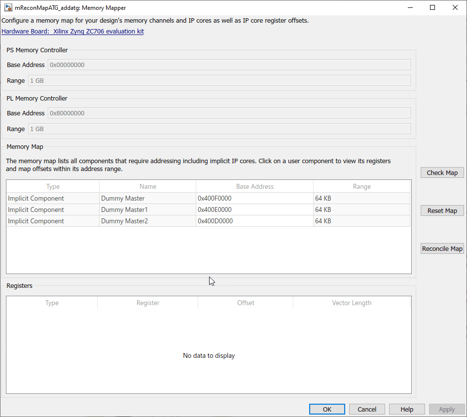
View and edit memory regions of an SoC application. Edit device base addresses and offsets for memory-mapped devices.

Using the Memory Mapper tool, you can:

  • View and edit base addresses, offsets, and memory locations of various channels and memory-mapped components in your design.

  • Check the memory map of your model for any conflicts between different memory channel configurations.

  • Reset the memory map to its default settings.

  • Reconcile an edited map to match model settings.

Open the Memory Mapper

  • In the Configuration Parameters dialog box, select Hardware Implementation from the left pane. Under Target hardware resources, select FPGA design (top-level) and click View/Edit Memory Map.

  • In the SoC Builder tool, in the Review Memory Map section, click View/Edit.

Examples

expand all

  • Consider a model with three masters (represented by Memory Traffic Generator blocks), connected to a Memory Controller block.

    To open the Memory Mapper tool, first open the Configuration Parameters dialog box, and then select Hardware Implementation from the left pane. Under Target hardware resources, select FPGA design (top-level) and click View/Edit Memory Map.

    The Memory Mapper lists the three masters in the design. Edit their base addresses as per your requirements. Add another channel to your model.

    The model consists of four memory channels, while the Memory Map section shows only three. To resolve this conflict, click Reconcile Map. This adds another line, which represents the added channel, to the memory map table.

  • Click Reset Map to create a new, autogenerated map. The base addresses of the channels are reset to a default value.

Related Examples

Parameters

expand all

This parameter is read-only.

This Parameter shows the targeted hardware board. Click the link to open the configuration parameters on the Hardware Implementation pane, and change any of the hardware configurations. To learn more about board configuration parameters, see Hardware Implementation Pane Overview.

PS Memory Controller

This parameter is read-only.

This parameter shows the base address of the external memory. This value is a 32-bit hexadecimal value.

This parameter is read-only.

This parameter shows the size of the external memory available for the selected hardware board. The memory size range is displayed in units of:

  • KB - kilobytes

  • MB - megabytes

  • GB - gigabytes

This value is derived from the hardware board selected in the configuration parameters.

PL Memory Controller

This parameter is read-only.

This parameter shows the base address of the external memory. This value is a 32-bit hexadecimal value.

This parameter is read-only.

This parameter shows the size of the external memory available for the selected hardware board. The memory size range is displayed in units of:

  • KB - kilobytes

  • MB - megabytes

  • GB - gigabytes

This value is derived from the hardware board selected in the configuration parameters.

Memory Map

Check that the memory map has no overlapping regions or registers, and that memory addresses are properly aligned.

Reset the memory map to its initial values.

Reconcile the memory map with the existing model. After adding or deleting a channel or a memory-mapped register to your model, click this button to synchronize between the model and the memory map. To verify that the reconciled memory map is valid, click Check Map after reconciling.

Note

Clicking Reconcile Map matches the memory map to the model but does not reset the base address values of the memory areas.

Version History

Introduced in R2019a
Go to top of page