Magic Formula Tire Force and Torque
Apply steady-state tire force and torque by using Magic Formula tire equations
Since R2021b

Libraries:
Simscape /
Multibody /
Forces and Torques
Description
The Magic Formula Tire Force and Torque block implements the combined slip steady-state Magic Formula model and can optionally include turn slip effects [1]. You can use the block for tires that have square-like cross-sections, such as the tires of passenger cars, trucks, and off-road vehicles.
The block calculates only the tire force and torque. To model the geometry and inertia properties of the tire, you must use a solid block, such as the Cylindrical Solid block. The Magic Formula tire model assumes that tires are disks, as shown in the diagram.
The follower frame is at the center of the tire and rotates with the tire. The contact frame is at the contact point between the tire and the contact surface. The tire block has two methods to compute the location and orientation of the contact frame. For scenarios that require only single-point contact, use the closest point method. For driving conditions that require multiple-point contacts, use the weighted penetration method. For more information, see Contact Frame Method.
The image shows the contact and follower frames of the tire at zero configuration.
The yaw, camber, and spin angles correspond to a y-x-z sequence rotation about the follower frame of the tire.
To specify the properties of a tire model, generate a scalar structure array by using
the simscape.multibody.tirread function and enter the array in the
Tire Parameters parameter. The structure array must include all
the necessary tire parameters, while any extra parameters are ignored in the tire
modeling. For the list of required parameters, see Required Tire Parameters. The block uses the
ISO sign conventions.
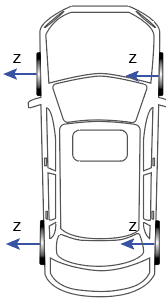
To specify the side of the vehicle to which a tire is mounted, use the Tire Side parameter. Specifying the wrong side can lead to unexpected simulation results. To correctly orient the tires on a vehicle, you must align the z-axes of the follower frames with the blue arrows shown in the diagram.
The signal output by the con port indicates whether the tire and the contact surface have a valid contact. If the tire and the surface are not in contact or the contact is not valid, all sensed outputs, such as the tire force, tire torque, and slip angle, become zero.
Ports
Geometry
Frame
Input
Output
Physical signal output port that provides a signal to determine
whether the tire and contact surface have a valid contact. When they are
in contact and the contact is valid, the signal equals
1, otherwise the signal equals
0.
If the follower frame is below the contact surface, the tire and the surface have an invalid contact and the block does not apply force and torque to the tire.
Dependencies
To enable this port, under Sensing, select Contact Signal.
Force/Torque
Physical signal output port that provides the magic formula tire force that is applied to the contact frame of the block. The output contains three parts:
Fx is the longitudinal force tangential to the contact surface at the contact point.
Fy is the lateral force which is orthogonal to the plane defined by Fx and Fz.
Fz is the normal force that is normal to the contact surface at the contact point.
The block resolves the force in the follower frame of the tire if you
set the Resolution Frame parameter to
Follower.
Dependencies
To enable this port, under Sensing > Force/Torque, select Tire Force.
Physical signal output port that provides the magic formula tire torque that is applied to the contact frame of the block. The output contains three parts:
Mx is the overturning moment.
My is the rolling resistance moment.
Mz is the aligning torque.
The block resolves the torque in the follower frame of the tire if you
set the Resolution Frame parameter to
Follower.
Dependencies
To enable this port, under Sensing > Force/Torque, select Tire Torque.
Physical signal output port that provides the distance from the contact point to the point of the resultant lateral force. The value has a unit of length.
You can use the pneumatic trail to compute the aligning torque, Mz.
Dependencies
To enable this port, under Sensing > Force/Torque, select Pneumatic Trail.
Slip
Physical signal output port that provides the ratio of the longitudinal slip velocity to the longitudinal speed of the tire.
Dependencies
To enable this port, under Sensing > Slip, select Longitudinal Slip.
Physical signal output port that provides the longitudinal slip saturated to always be within the limits defined by the KPUMIN and KPUMAX parameters.
Dependencies
To enable this port, under Sensing > Slip, select Saturated Longitudinal Slip.
Physical signal output port that provides the angle of the right triangle made by the lateral slip velocity, Vsy and the longitudinal speed, Vx. The value has a unit of angle.

Dependencies
To enable this port, under Sensing > Slip, select Slip Angle.
Physical signal output port that provides the slip angle saturated to always be within the limits defined by the ALPMIN and ALPMAX parameters. The value has a unit of angle.
Dependencies
To enable this port, under Sensing > Slip, select Saturated Slip Angle.
Physical signal output port that provides the ratio of the tire yaw velocity to the magnitude of the tire velocity in the xy-plane of the contact frame. The value has a unit of angle/length.
Turn slip is useful when modeling low speed cornering, such as parking maneuvers.
Dependencies
To enable this port, under Sensing > Slip, select Turn Slip.
Linear Velocity
Physical signal output port that provides the component of the relative velocity between the follower frame and the contact point on the base geometry along the x-direction of the contact frame. The value has a unit of length/time.
Dependencies
To enable this port, under Sensing > Linear Velocity, select Relative Longitudinal Velocity.
Physical signal output port that provides the component of the relative velocity between the follower frame and the contact point on the base geometry along the y-direction of the contact frame. The value has a unit of length/time.
Dependencies
To enable this port, under Sensing > Linear Velocity, select Relative Lateral Velocity.
Physical signal output port that provides the component of the relative velocity between the slip point on the tire and the coincident point on the base geometry along the x-direction of the contact frame. The value has a unit of length/time.
Dependencies
To enable this port, under Sensing > Linear Velocity, select Longitudinal Slip Velocity.
Physical signal output port that provides the component of the relative velocity between the slip point on the tire and the coincident point on the base geometry along the y-direction of the contact frame. The value has a unit of length/time.
Dependencies
To enable this port, under Sensing > Linear Velocity, select Lateral Slip Velocity.
Yaw
Physical signal output port that provides the first derivative of the yaw angle. The value has a unit of angle/time.
Dependencies
To enable this port, under Sensing > Yaw, select Velocity.
Camber
Physical signal output port that provides the camber angle of the tire. The value has a unit of angle.
Dependencies
To enable this port, under Sensing > Camber, select Angle.
Physical signal output port that provides the camber angle of the tire saturated to always be within the limits defined by the CAMMIN and CAMMAX parameters. The value has a unit of angle.
Dependencies
To enable this port, under Sensing > Camber, select Angle.
Physical signal output port that provides the first derivative of the camber angle. The value has a unit of angle/time.
Dependencies
To enable this port, under Sensing > Camber, select Velocity.
Spin
Physical signal output port that provides the first derivative of the spin angle. The value has a unit of angle/time.
Dependencies
To enable this port, under Sensing > Spin, select Velocity.
Tire Radius
Physical signal output port that provides the free radius of the tire. The radius increases as the tire rotates faster. The value has a unit of length.
Dependencies
To enable this port, under Sensing > Tire Radius, select Free Radius.
Physical signal output port that provides the distance from the center of the tire to the contact point between the tire and the contact surface. The value has a unit of length.
Dependencies
To enable this port, under Sensing > Tire Radius, select Loaded Radius.
Physical signal output port that provides the distance from the follower frame to the slip point. The value has a unit of length.
Dependencies
To enable this port, under Sensing > Tire Radius, select Effective Rolling Radius.
Physical signal output port that provides the difference between the free radius output from the romega port and the loaded radius output from the rl port. The value has a unit of length.
Dependencies
To enable this port, under Sensing > Tire Radius, select Radial Deflection.
Friction
Physical signal output port that provides the longitudinal friction coefficient of the tire computed by the magic formula equations.
Dependencies
To enable this port, under Sensing > Friction, select Longitudinal Friction Coefficient.
Physical signal output port that provides the lateral friction coefficient of the tire computed by the magic formula equations.
Dependencies
To enable this port, under Sensing > Friction, select Lateral Friction Coefficient.
Contact Frame
Physical signal port that outputs a 3-by-3 rotation matrix that maps the vectors in the contact frame to vectors in the reference frame of the base geometry. The output signal is resolved in the reference frame associated with the base geometry.
Dependencies
To enable this port, in the Sensing > Contact Frame section, select Base Rotation.
Physical signal port that outputs a 3-by-1 vector that contains the coordinates of the origin of the contact frame resolved in the reference frame of the base geometry.
Dependencies
To enable this port, in the Sensing > Contact Frame section, select Base Translation.
Physical signal port that outputs a 3-by-3 rotation matrix that maps vectors in the contact frame to vectors in the reference frame of the follower geometry. The output signal is resolved in the reference frame associated with the follower geometry.
Dependencies
To enable this port, in the Sensing > Contact Frame section, select Follower Rotation.
Physical signal port that outputs a 3-by-1 vector that contains the coordinates of the origin of the contact frame resolved in the reference frame of the follower geometry.
Dependencies
To enable this port, in the Sensing > Contact Frame section, select Follower Translation.
Parameters
More About
References
[1] Pacejka, Hans B., and Igo Besselink. Tire and Vehicle Dynamics. 3rd. Engineering Automotive Engineering. Amsterdam: Elsevier/Butterworth-Heinemann, 2012.
[2] Besselink, I. J.M., A. J.C. Schmeitz, and H. B. Pacejka. “An Improved Magic Formula/Swift Tyre Model That Can Handle Inflation Pressure Changes.” Vehicle System Dynamics 48, no. sup1 (December 2010): 337–52. https://doi.org/10.1080/00423111003748088.
[3] van der Hofstad, R. H. M. T. “Study on improving the MF-Swift tyre model.” (2010).