Analyze Results for Dead Logic Analysis
This example demonstrates how to isolate potential causes of dead logic using the ProtectedDivde model. Dead logic detection finds unreachable objectives in the model that cause the model element to remain inactive.
Workflow
The ProtectedDivde model demonstrates some of the common patterns that often lead to dead logic in a model. The six subsystems in the model represent a different pattern. These subsystems are:
Conditional execution of a subsystem
Short-circuiting of a logical operator block during analysis
Parameter values treated as constants
Library-linked blocks
Upstream blocks
Restrictions on signal ranges
Run Dead Logic Analysis
Follow these steps to run the dead logic analysis:
1. Open the model ProtectedDivde.
open_system('ProtectedDivde');

2. In the Apps pane, open Design Verifier.
3. On the Design Verifier tab, click Error Detection Settings.
4. In the Configuration Parameters dialog box:
a. Enable the Dead logic (partial) option.
b. Clear the Run exhaustive analysis option, if it is selected.
c. Set Coverage objectives to be analyzed to Condition Decision option. The available options from the drop-down menu are Decision, Condition Decision, and MCDC.
5. In the Design Verifier tab, Click Detect Design Errors.
Analyze and Review the Results
The software analyzes the model for dead logic and displays the results in the Results Summary window. The results indicate that 19 of the 44 objectives are dead logic.

Highlight Analysis Results in the Subsystem Blocks
This section explains the common patterns that lead to dead logic in the ProtectedDivde model. In the Results Summary window, click on Highlight analysis results on model. The subsystems with dead logic are highlighted in red. These subsystems are:
ConditionallyExecuteInputs
ShortCircuiting
Parameters
Library
CascadingDeadLogic
ConditionGreaterThan0
The subsystems in the ProtectedDivde model explain these patterns. Each subsystem block highlighted in red has a dead logic red. Consider each subsystem one by one to analyze and highlight the results.
1. Conditional Execution of a Subsystem
If your model includes Switch or Multiport Switch blocks and the conditional input branch execution parameter is set to On, the conditional execution can often cause unexpected dead logic. Open the ConditionallyExecuteInputs subsystem and click the AND block highlighted in red. The Results window summarizes the dead logic.

In this subsystem, the Conditional input branch execution parameter is set to On. The AND Logical Operator block is conditionally executed, which causes the dead logic for the subsystem.
2. Short-Circuiting of a Logical Operator Block During Analysis
Simulink Design Verifier treats logic blocks as if they are short-circuiting when analyzing for dead logic. Open the ShortCircuiting subsystem, and click the AND block highlighted in red. The Results window summarizes the dead logic.

In this model, if In3 is false, the software ignores the third input due to the short-circuiting. This is suggested as a potential explanation for the dead logic in the Results window.
3. Parameter Values Treated as Constants
If your model contains parameters, Simulink Design Verifier treats the values as constants by default, which might cause dead logic in the model. In these cases, consider configuring these parameters to be tuned during analysis. Open the ShortCircuiting subsystem and click the Switch block highlighted in red. The Results window summarizes the dead logic.

Here, all of the parameters are set to zero. This causes the dead logic for the Less Than block.
4. Library-Linked Blocks
The ProtectedDivide library subsystem has protection for division by zero. Library blocks may be written with defensive conditions that are redundant in some of the locations where they are used. In some cases, this may cause dead logic. Open the Library block, and click the ProtectedDivide subsystem highlighted in red. In this case, the inputs to the ProtectedDivide library subsystem can never experience a division by zero. This causes the guarding logic to be dead. The Equal block shows the dead logic. The Results window summarizes the dead logic.

Consider justifying the dead logic that arises from those library blocks.
5. Upstream Blocks
When a particular block has dead logic, this often leads to a cascading effect that causes downstream blocks to also have dead logic. Open the CascadingDeadLogic subsystem and click the Less Than block highlighted in red. The Results window summarizes the dead logic.

The dead logic in the Less Than block causes the dead logic in the corresponding downstream blocks. It is therefore often helpful to review the upstream dead logic before reviewing any downstream dead logic.
6. Restrictions on Signal Ranges
Root-level Inport blocks with minimum and maximum values as constraints and Test Condition blocks in the test generation may cause dead logic. For example, consider the ConditionGreaterThan0 Switch block, where the second Inport block has a minimum and maximum range of 1 and 100, respectively. This causes the Switch block in this subsystem to have dead logic, because the constrained range means the signal will always be greater than 0.

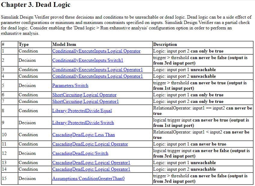
View the Analysis Report
In the Results summary window, click HTML to view the detailed analysis report. The report summarizes all of the dead logic results in the model.
To perform an exhaustive analysis for dead logic, in the Configuration Parameters Window in the Design Error Detection pane, select Run exhaustive analysis. The software stores the detailed analysis results in the DeadLogic field in the Simulink Design Verifier data files. You can use the data file to further analyze the results.
Note: Defect Checker automatically invokes dead logic, out of bound array access, division by zero, integer overflow, and specified minimum and maximum value violations checks. To specify checks set Defect Checker to off.
Use Model Slicer to Find Parameters Impact on Blocks
You can use Model Slicer to find the parameters which could have an impact on a particular block by following these steps:
a. Create an object of SLSlicerAPI.ParameterDependence using Model Slicer.
slicerObj = slslicer('ProtectedDivde');
pd = slicerObj.parameterDependence;
b. Find the parameters affecting the Product block.
params = parametersAffectingBlock(pd, 'ProtectedDivde/Divide');

The image above displays the parameters returned by the function parametersAffectingBlock which have an impact on the Product block. The list of parameters returned by the function can be considered for tuning.
c. Perform clean-up to exit compile state of the model.
slicerObj.terminate;