Estimate Battery Impedance Using Signal Generator Blocks
This example shows how to use frequency response estimation to estimate the impedance of a battery modeled using Simscape™ Battery™ software. To generate a perturbation signal for frequency response estimation (FRE), you can use the signal generation blocks from Simulink® Control Design™ software. You can use the PRBS Signal Generator block to generate PRBS perturbation signals, which provide fast estimation in power electronic applications. This example also shows how to process the experiment data by using a data logging block and the frestimate function to derive the battery cell impedance. To examine the impedance measurement, you can compare against a transfer function from manual derivation.
Open Model
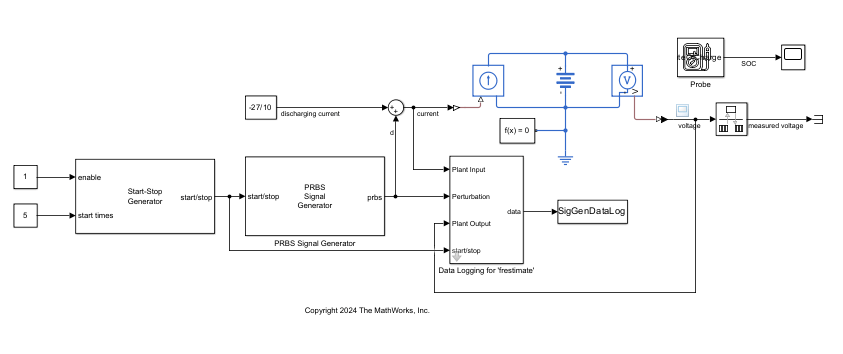
The Simulink model uses a Battery Equivalent Circuit block and discharges from different SOC levels at a constant current value.
Open the model.
mdl_siggen = "BatteryImpedanceSigGenFRE";
open_system(mdl_siggen)
Derive Impedance Manually
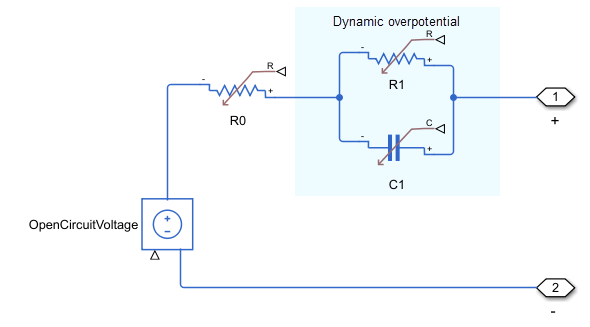
For this model, the parameter values of the Battery Equivalent Circuit block describe the circuit in this image.

The Simulink model has one time constant that corresponds to the resistor-capacitor pair represented in the image by the R1 and C1 blocks. Based on the circuit diagram, this transfer function describes the impedance:
.
At an SOC level of 100%, you can manually derive the transfer function using the values defined in the block parameters.
R0 = 0.0085;
R1 = 0.017;
Tau1 = 0.39;
Z_soc100 = tf([Tau1*R0 R0+R1],[Tau1 1]);
Ts = 0.005;
Z_soc100d = c2d(Z_soc100,Ts);
Measure and Process Impedance Data
The model generates the perturbation signal using the PRBS Signal Generator block and logs the circuit response using the Data Logging for 'frestimate' block.
Simulate the model.
sim(mdl_siggen)
The model logs the response to the perturbation signal in the SigGenDataLog variable. Using this logged data, you can estimate the battery cell impedance with the frestimate function.
SigGenDataLog
SigGenDataLog = struct with fields:
           Ready: [1×1 timeseries]
    Perturbation: [1×1 timeseries]
      PlantInput: [1×1 timeseries]
     PlantOutput: [1×1 timeseries]
            Info: [1×1 struct]
Specify the frequency range and estimate the impedance.
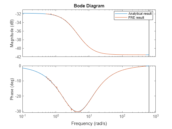
sys_estim = frestimate(SigGenDataLog,logspace(-0.3,2.7,500),'rad/s');To compare the estimation result with the derived transfer function, plot the Bode response.
figure
bodeplot(Z_soc100d,sys_estim);
legend("Analytical result","FRE result",Location="best");

The analytical and estimated models are a close match.
Estimate Equivalent Circuit Parameters from Frequency Response Data
For a fixed structure equivalent circuit, you can estimate the component parameters of the circuit using System Identification Toolbox™ software.
To estimate the parameters, create an idtf object that represents the initial transfer function form specified in the Derive Impedance Manually section.
Z_ini = idtf([0.005 0.1],[0.5 1]);
To estimate a fit for the frequency response data model sys_estim, use the tfest function.
sys_tf = tfest(sys_estim,Z_ini)
sys_tf =

  0.0085 s + 0.06566
  ------------------
       s + 2.57

Continuous-time identified transfer function.

Parameterization:
   Number of poles: 1   Number of zeros: 1
   Number of free coefficients: 3
   Use "tfdata", "getpvec", "getcov" for parameters and their uncertainties.

Status:
Estimated using TFEST on frequency response data "sys_estim".
Fit to estimation data: 98.86%
FPE: 5.5e-09, MSE: 5.435e-09

Model Properties
Plot the Bode response.
figure
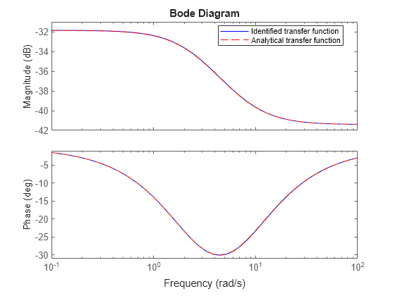
bodeplot(sys_tf,"b-",Z_soc100,"r--");
legend("Identified transfer function",...
    "Analytical transfer function",Location="best");

The response of the two transfer functions matches. You can also directly identify the equivalent circuit parameters from the identified transfer function.
Obtain the transfer function data from the identified model.
[num,den] = tfdata(sys_tf,"v");To compute the circuit parameters, compare the data from the identified transfer function with the coefficients of the manually derived transfer function.
Tau1
Tau1 =
0.3900
Tau1_est = den(1)/den(2)
Tau1_est =
0.3892
R0
R0 =
0.0085
R0_est = (num(1)/den(2))/Tau1_est
R0_est =
0.0085
R1
R1 =
0.0170
R1_est = num(2)/den(2) - R0_est
R1_est =
0.0171
All the values match closely with the parameters defined in the Battery Equivalent Circuit block. These results demonstrate how you can obtain key battery cell parameters from the FRE-based impedance measurements.
Close the model.
close_system(mdl_siggen,0);
See Also
frestimate | Sinestream Signal
Generator | PRBS Signal
Generator