Control Real-Time PID Autotuning in Simulink
Deploying the PID autotuner blocks lets you tune your system in real time without Simulink® in the loop. However, it can be useful to run the autotuning algorithm on hardware while controlling the experiment from Simulink.
One way to do so is to use a model that contains a PID controller and a PID autotuner block, and run this model in external simulation mode. External mode allows communication between the Simulink block diagram and the standalone program that is built from the generated code. In this mode, Simulink serves as a real-time monitoring interface in which you can interact with the tuning algorithm running on hardware. For instance, you can start and stop the experiment or change tuning goals from the Simulink interface while the model is running.
When tuning in external mode, you can deploy the experiment algorithm only, such that the PID tuning part of the calculation is performed in Simulink. Doing so can save memory on your target hardware. Running the PID autotuning algorithm in external mode requires a code-generation product such as Simulink Coder™.
Simulink Model for External-Mode Tuning
A Simulink model for PID autotuning in external mode resembles the following illustration.
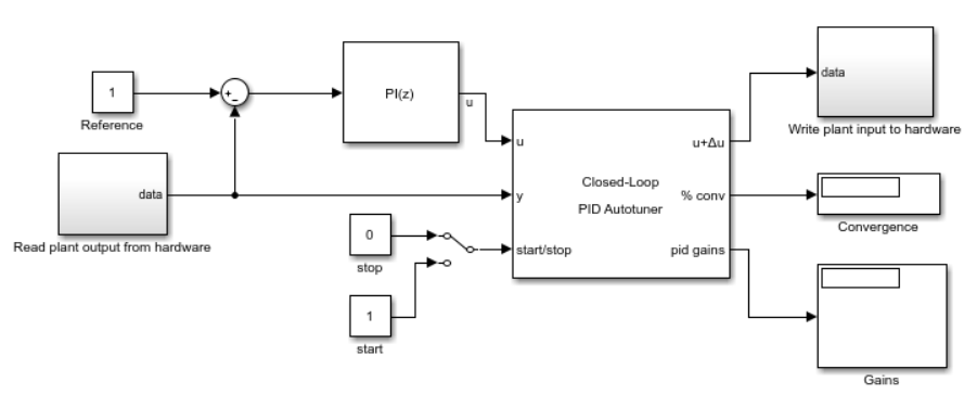
Here, the blocks marked Read plant output from hardware and
Write plant input to hardware represent hardware interfaces that
read data from or write data to your physical plant. When you are ready for tuning, you
run this model in external simulation mode.
Bumpless Transfer for Open-Loop Tuning
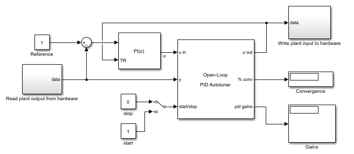
When you use the Open-Loop PID Autotuner, if your controller includes integrator action, consider implementing signal tracking to avoid integrator windup during the tuning experiment. Signal tracking enables the PID controller to continue to track the real plant input while it is out of the loop. Without it, your system can experience a bump when the control loop is closed at the end of the tuning process.
If your PID controller is a Simulink PID Controller block, you can use the Enable tracking mode parameter of the controller block to avoid this bump. The following diagram illustrates a module containing an Open-Loop PID Autotuner block and a PID Controller block with tracking mode configured. The plant input feeds into the tracking input of the controller block.
For external-mode tuning, you configure the start-stop signal
as described in
PID Autotuning for a Plant Modeled in Simulink. The models
illustrated here use a simple switch with a binary signal to start and stop the
experiment manually.
You also configure controller parameters, tuning goals, and experiment parameters as described in PID Autotuning for a Plant Modeled in Simulink.
Run the Model and Tune the Controller Gains
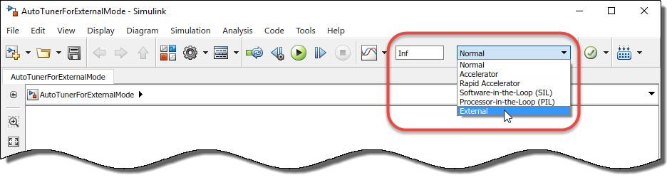
After configuring the block parameters for the experiment, in the model, select
external mode, set the simulation time to infinite, and
run the model.
Simulink compiles the model and deploys it to your connected hardware.
If you have configured the
start/stopsignal to begin and end the tuning process at specific times, allow the simulation to run through the end of the experiment.If you have configured a manual
start/stopsignal, begin the experiment when your plant has reached steady-state. Observe the signal at the% convoutput, and stop the experiment when the signal stabilizes near 100%.
When tuning is complete, examine and validate the tuned gains as described in PID Autotuning for a Plant Modeled in Simulink.
For a more detailed example that illustrates the use of external mode to control the autotuning process via Simulink, see Tune PID Controller in Real Time Using Open-Loop PID Autotuner Block.
Reduce Memory Footprint When Using External Mode
The autotuner blocks contain two modules, one that performs the real-time frequency-response estimation, and one that uses the resulting estimated response to tune the PID gains. When you run a Simulink model containing the block in the external simulation mode, by default both modules are deployed. You can save memory on the target hardware by deploying the estimation module only. In this case, the tuning algorithm runs on the Simulink host computer instead of the target hardware. To do so, use the Reduce memory and avoid task overrun option in the autotuner block. When this option is selected, the deployed algorithm uses about a third as much memory as when the option is cleared.
The PID gain calculation demands more computational load than the frequency-response estimation. For fast controller sample times, some hardware might not finish the gain calculation within one execution cycle. Therefore, when using hardware with limited computing power, selecting this option lets you tune a PID controller with a fast sample time.
Additionally, when you enable this option, there can be a delay of several sampling periods between when the tuning experiment ends and when the new PID gains arrive at the pid gains output port. Before pushing gains to the controller, first confirm the change at the pid gains output port instead of using start/stop signal as the trigger for the update.
Caution
When you use this option, the model must be configured such that numeric block parameters are tunable in generated code, not inlined. To specify tunable parameters:
In the model editor: In Configuration Parameters, in Code Generation > Optimization, set Default parameter behavior to
Tunable.At the command line: Use
set_param(mdl,'DefaultParameterBehavior','Tunable').
See Also
Closed-Loop PID Autotuner | Open-Loop PID Autotuner