Transfer Fcn
Model linear system as transfer function
Libraries:
Simulink /
Continuous
Description
The Transfer Fcn block models a linear system by a transfer function of the
Laplace-domain variable s. The block can model single-input
single-output (SISO) and single-input multiple-output (SIMO) systems.
Conditions for Using This Block
The Transfer Fcn block assumes the following conditions:
The transfer function has the form
where u and y are the system input and outputs, respectively, nn and nd are the number of numerator and denominator coefficients, respectively. num(s) and den(s) contain the coefficients of the numerator and denominator in descending powers of s.
The order of the denominator must be greater than or equal to the order of the numerator.
For a multiple-output system, all transfer functions have the same denominator and all numerators have the same order.
Modeling a Single-Output System
For a single-output system, the input and output of the block are scalar time-domain signals. To model this system:
Enter a vector for the numerator coefficients of the transfer function in the Numerator coefficients field.
Enter a vector for the denominator coefficients of the transfer function in the Denominator coefficients field.
Modeling a Multiple-Output System
For a multiple-output system, the block input is a scalar and the output is a vector, where each element is an output of the system. To model this system:
Enter a matrix in the Numerator coefficients field.
Each row of this matrix contains the numerator coefficients of a transfer function that determines one of the block outputs.
Enter a vector of the denominator coefficients common to all transfer functions of the system in the Denominator coefficients field.
Specifying Initial Conditions
A transfer function describes the relationship between input and output in Laplace (frequency) domain. Specifically, it is defined as the Laplace transform of the response (output) of a system with zero initial conditions to an impulse input.
Operations like multiplication and division of transfer functions rely on zero initial state. For example, you can decompose a single complicated transfer function into a series of simpler transfer functions. Apply them sequentially to get a response equivalent to that of the original transfer function. This will not be correct if one of the transfer functions assumes a non-zero initial state. Furthermore, a transfer function has infinitely many time domain realizations, most of whose states do not have any physical meaning.
For these reasons, Simulink® presets the initial conditions of the Transfer Fcn
block to zero. To specify initial conditions for a given transfer function, convert
the transfer function to its controllable, canonical state-space realization using
tf2ss. Then, use the State-Space block. The
tf2ss utility provides the A,
B, C, and D matrices
for the system.
For more information, type help tf2ss or
see the Control System Toolbox™ documentation.
Transfer Function Display on the Block
The Transfer Fcn block displays the transfer function depending on how you specify the numerator and denominator parameters.
If you specify each parameter as an expression or a vector, the block shows the transfer function using the specified coefficients for the powers of s. If you specify a variable in parentheses, the block evaluates the variable.
For example, if you specify the Numerator coefficients parameter value as
[3 2 1]and the Denominator coefficients parameter value as(den), wheredenis a workspace variable with a value of[7 5 3 1], the block displays the equation using the specified values.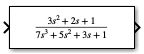
Tip
When the block size is too small to accommodate the full numerator or denominator, the block icon displays the numerator as
num(s)and the denominator asden(s).
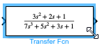
If you want the block to show the equation for the transfer function it implements, resize the block by dragging a corner.
If you specify each parameter as a variable, the block shows the variable name followed by
(s).For example, if you specify the Numerator coefficients parameter as
numand the Denominator coefficients parameter asden, the block icon shows the numerator of the transfer function asnum(s)and the denominator asden(s).
Examples
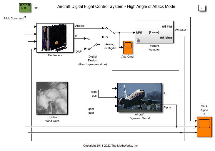
Designing a High Angle of Attack Pitch Mode Control
Use Control System Toolbox™, Simulink® Control Design™ and Aerospace Blockset™ to design a flight control system for the longitudinal motion of aircraft. You develop a controller that enables stable operation at high angles of attack with minimal pilot workload.

Model an Anti-Lock Braking System
Model a simple Anti-Lock Braking System (ABS). The model simulates the dynamic behavior of a vehicle under hard braking conditions. The model represents a single wheel, which may be replicated a number of times to create a model for a multi-wheel vehicle.

Inverted Pendulum with Animation
Use Simulink® to model and animate an inverted pendulum system. An inverted pendulum has its center of mass above its pivot point. To stably maintain this position, the system implements control logic to move the pivot point below the center-of mass as the pendulum starts to fall. The inverted pendulum is a classic dynamics problem used to test control strategies.
Ports
Input
Output
Parameters
Block Characteristics
Extended Capabilities
Version History
Introduced before R2006a