Modeling Clutch Lock-Up Using If Blocks
This example shows how to use If/Else subsystems to build a clutch model. An 'If' subsystem models the clutch dynamics in the locked position while an 'Else' subsystem models the unlocked position. One or the other is enabled using the 'If' block. The dot-dashed lines from the 'If' block denote control signals, which are used to enable If/Else (or other conditional) subsystems. Checking any of the boxes on the GUI produces a plot of any of the selected variables (versus time).
Analysis and Physics
The clutch system in this example consists of two plates that transmit torque between the engine and transmission. There are two distinct modes of operation:
1) slipping - the two plates have differing angular velocities
2) lockup - the two plates rotate together.
Handling the transition between these two modes presents a modeling challenge. As the system loses a degree of freedom upon lockup, the transmitted torque goes through a step discontinuity. The magnitude of the torque drops from the maximum value supported by the friction capacity to a value that is necessary to keep the two halves of the system spinning at the same rate. The reverse transition, break-apart, is likewise challenging, as the torque transmitted by the clutch plates exceeds the friction capacity.
Note: You can find a detailed analysis of this system, including equations and diagrams, in the example for the clutch model with enabled subsystems.
Modeling
You can use the following two methods for solving this problem:
1) Compute the clutch torque transmitted at all times, and employ this value directly in the model.
2) Use two different dynamic models and switch between them at the appropriate times.
Simulink® can model either method. In this example, we describe a simulation for the second method. Switching between two dynamic models must be performed with care to ensure that the initialized states of the new model match the state values immediately prior to the switch. In either approach, Simulink facilitates accurate simulation due to its ability to recognize the precise moments at which transitions between lockup and slipping occur.
Running the Simulation
When the model is open, to run the simulation, click Run.
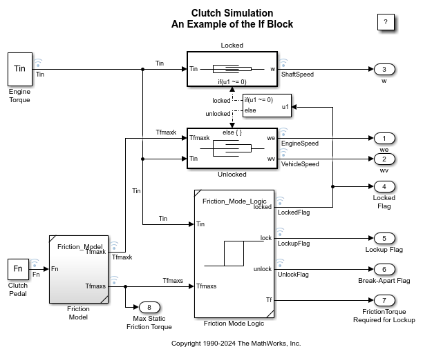
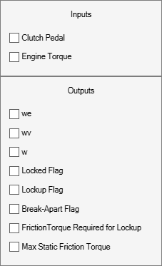
Figure 1: Top level diagram for the clutch model
Note: The model logs relevant data to MATLAB® workspace in a structure called
sldemo_clutch_if_output. Logged signals have a blue indicator. For information about signal logging, see Mark Signals for Logging.
The 'If' Block
The 'If' block uses the LockedFlag signal to switch between the 'Locked' and 'Unlocked' subsystems. Double-click the 'If' block in the model to set its parameters (see Figure 2). LockedFlag represents the status of the clutch. LockedFlag = 1 if the clutch is locked and LockedFlag = 0 if the clutch is unlocked.
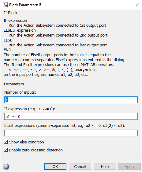
Figure 2: Setting 'If' block parameters
Results
The inputs for this model are the same as for the model that uses enabled subsystems (sldemo_clutch). System velocities behave as shown in Figure 3 below. As expected, the results obtained from sldemo_clutch and sldemo_clutch_if are identical.
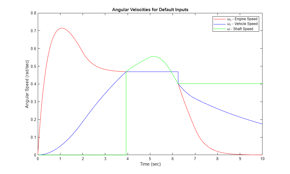
Figure 3: Angular velocities of the engine, vehicle and shaft for default inputs
Closing Model
Close the model. Clear generated data.

Conclusions
This example shows how to use 'If' blocks in Simulink to model a system with topological discontinuities. This is an alternative to using enabled subsystems.