System Definition and Layout
The top-level system layout of a Simulink® model is a common context that many engineering teams can use and is the basis for many tasks in the Model-Based Design paradigm: analysis, design, test, and implementation. You define a system at the top level by identifying the structure and individual components. You then organize your model in a hierarchical manner that corresponds to the components. Then you define interfaces for each component and the connections between components.
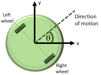
The featured model in this tutorial is a flat robot that can move or rotate with the help of two wheels, similar to a home vacuuming robot. This model assumes that the robot moves in one of two ways:
Linear — Both wheels turn in the same direction with the same speed and the robot moves linearly.
Rotational — The wheels turn in opposite directions with the same speed and the robot rotates in place.
Each type of motion starts from a resting state, that is, both rotational and linear speeds are zero. With these assumptions, the linear and rotational motion components can be modeled separately.
Determine Modeling Objectives
Before designing a model, consider your goals and requirements. The goals dictate both the structure and the level of detail for the model. If the goal is simply to figure out how fast the robot can go, modeling just for linear motion is sufficient. If the goal is to design a set of inputs for the device to follow a given path, then the rotational component is involved. If obstacle avoidance is a goal, then the system needs a sensor. This tutorial builds a model with the goal of designing sensor parameters so that the robot stops in time when it detects an obstacle in its path. To achieve this goal, the model must:
Determine how quickly the robot stops when the motors stop
Provide a series of commands for linear and rotational motion so that the robot can move in a two-dimensional space
The first modeling objective enables you to analyze the motion so you can design the sensor. The second objective enables you to test your design.
Identify System Components and Interfaces
Once you understand your modeling requirements, you can begin to identify the components of the system. Identifying individual components and their relationships within a top-level structure help build a potentially complex model systematically. You perform these steps outside Simulink before you begin building your model.
This task involves answering these questions:
What are the structural and functional components of the system? When a layout reflects the physical and functional structure, it helps you to understand, build, communicate, and test the system. This becomes more important when parts of the system are to be implemented in different stages in the design process.
What are the inputs and outputs for each component? Draw a picture showing the connections between components. This picture helps you to visualize signal flow within the model, identify the source and sink of each signal, and determine if all necessary components exist.
What level of detail is necessary? Include major system parameters in your diagram. Creating a picture of the system can help you identify and model the parts that are essential to the behaviors you want to observe. Each component and parameter that contributes to the modeling goal must have a representation in the model, but there is a tradeoff between complexity and readability. Modeling can be an iterative process. You can start with a high-level model with few details and then gradually increase complexity where required.
It is often beneficial to consider the following:
What parts of the system need testing?
What is the test data and success criteria?
Which outputs are necessary for analysis and design tasks?
Identify Robot Motion Components
The system in this tutorial defines a robot that moves with two electric wheels in two dimensions. It includes:
Linear motion characteristics
Rotational motion characteristics
Transformations to determine the location of the system in two dimensions
A sensor to measure the distance of the robot from an obstacle
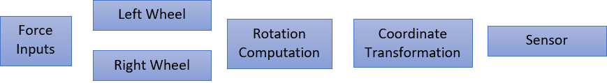
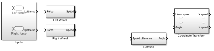
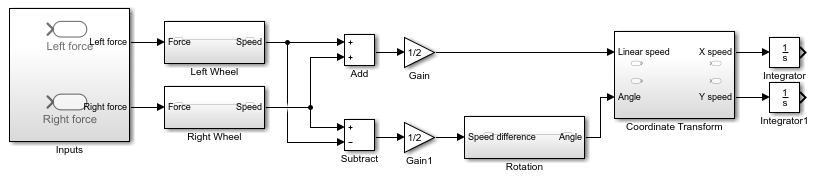
The model for this system includes two identical wheels, input forces applied to the wheels, rotational dynamics, coordinate transformation, and a sensor. The model uses a Subsystem to represent each component:
Open a new Simulink model. See Open New Model.
Open the Library Browser. See Open Simulink Library Browser.
Add Subsystem blocks. Drag five Subsystem blocks from the Ports & Subsystems library to the new model.
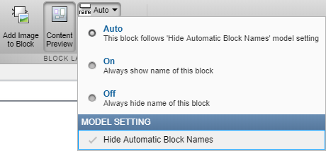
Click a subsystem. In the Format tab, click the Auto drop-down list. Clear the Hide Automatic Block Names check box.
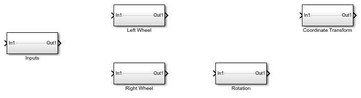
Arrange and rename the Subsystem blocks as shown. To change block names, double-click the block name and edit the text.
Define Interfaces Between Components
Identify input and output connections between subsystems. Input and output values change dynamically during a simulation. Lines connecting blocks represent data transfer. This table shows the inputs and outputs for each component.
| Block | Input | Output | Related Information |
|---|---|---|---|
| Inputs | None | Force to right wheel Force to left wheel | Not applicable |
| Right wheel | Force to right wheel | Right wheel velocity | Directional, negative means reverse direction |
| Left wheel | Force to left wheel | Left wheel velocity | Directional, negative means reverse direction |
| Rotation | Velocity difference between right and left wheels | Rotational angle | Measured counterclockwise |
| Coordinate Transformation | Normal speed Rotational angle | Velocity in X Velocity in Y | Not applicable |
| Sensor | X coordinate Y coordinate | None | No block necessary for modeling |
Some block inputs do not exactly match block outputs. Therefore, in addition to the dynamics of the individual components, the model must compute the following:
Input to the rotation computation — Subtract the velocities of the two wheels and divide by two.
Input to the coordinate transformation — Average the velocities of the two wheels.
Input to the sensor — Integrate the outputs of the coordinate transformation.
The wheel velocities are always equal in magnitude and the computations are accurate within that assumption.
Add the necessary components and finalize connections:
Add the necessary input and output ports to each subsystem. Double-click a Subsystem block.
Each new Subsystem block contains one Inport (In1) and one Outport (Out1) block. These blocks define the signal interface with the next higher level in a model hierarchy.
Each Inport block creates an input port on the Subsystem block, and each Outport block creates an output port. The model reflects the names of these blocks as the input/output port names. Add more blocks for additional input and output signals. On the Simulink Editor toolbar, click the Navigate Up To Parent button
 to return to the top level.
 For each block, add and rename Inport and Outport blocks.
When copying an Inport block to create a new one, use the Paste (Ctrl+V) option.
Compute required inputs to the Coordinate Transform and Rotation subsystems from the left wheel and right wheel velocities.
Compute the Linear speed input to the Coordinate Transform subsystem. Add an Add block from the Math Operations library and connect the outputs of the two-wheel components. Add a Gain block and set the gain parameter to
1/2. Connect the output of the Add block to this Gain block.Compute the Speed difference input to the Rotation subsystem. Add a Subtract block from the Math Operations library. Connect the right wheel velocity to the + input and the left wheel velocity to the - input. Connect the outputs of the two wheel components. Add a Gain block and set the gain parameter to
1/2. Connect the output of the Subtract block to this Gain block.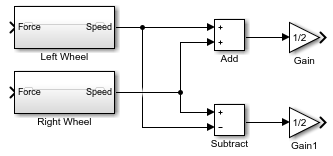
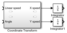
Compute the X and Y coordinates from the X and Y velocities. Add two Integrator blocks from the Continuous library and connect the outputs of the Coordinate Transform block. Leave initial conditions of the Integrator blocks set to
0.
Complete the connections for the system.
Parameters and Data
Determine the parameters that are part of the model and their values. Use modeling goals to determine whether these values are always fixed or change from simulation to simulation. Parameters that contribute to the modeling goal require explicit representation in the model. This table helps determine the level of detail when modeling each component.
| Parameter | Block | Symbol | Value | Type |
|---|---|---|---|---|
| Mass | Left Wheel Right Wheel | m | 2.5 kg | Variable |
| Rolling resistance | Left Wheel Right Wheel | k_drag | 30 Ns2/m | Variable |
| Robot radius | Rotation | r | 0.15 m | Variable |
| Initial angle | Rotation | None | 0 rad | Fixed |
| Initial velocities | Left Wheel Right Wheel | None | 0 m/s 0 m/s | Fixed |
| Initial (X, Y) coordinates | Integrators | None | (0, 0) m | Fixed |
Simulink uses the MATLAB® workspace to evaluate parameters. Set these parameters in the MATLAB command window:
m = 2.5;
k_drag = 30;
r = 0.15;